Advertisement
Available languages
Available languages
Quick Links
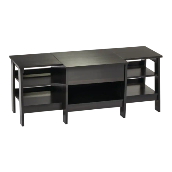
Trestle Entertainment Unit
Product No. 168-0043-0
Model No. 424230
Assembly Instructions
Toll free: 1-877-483-6759
IMPORTANT: Please read this manual carefully before beginning assembly of this product.
Keep this manual for future reference.
Advertisement

Subscribe to Our Youtube Channel
Related Manuals for for Living 424230


Summary of Contents for for Living 424230
- Page 1 Trestle Entertainment Unit Product No. 168-0043-0 Model No. 424230 Assembly Instructions Toll free: 1-877-483-6759 IMPORTANT: Please read this manual carefully before beginning assembly of this product. Keep this manual for future reference.
- Page 2 When it comes to products for your home, it's essential they stand up to the realities of everyday family life. Designed with your family in mind, For Living® products combine timeless style and family-friendly features. Now you can focus on what's important—creating lasting memories with your family.
- Page 3 Table of Contents Important Safety Instructions Parts List Assembly Preparation Assembly 7-22 Cleaning and Maintenance Technical Data Warranty Warning! To reduce the risk of serious injury, read the following safety instructions before assembling and using the entertainment unit. Caution! Always keep children under close supervision while they are using or around this product. Never leave children unattended.
- Page 4 Product No. 168-0043-0 Model No. 424230 • Right front leg - 1 Left top - 1 Top molding - 2 Right back leg - 1 Molding - 4 Right centre leg - 1 Left brace - 1 Long skirt - 1...
- Page 5 Short skirt - 2 Large hidden cam - 47 Small hidden cam - 4 Drawer bottom - 1 Cam screw - 43 Drawer front - 1 Double dowel - 4 Left drawer side - 1 WARNING • AVERTISSEMENT Never use this furniture with a Ne jamais utiliser ce meuble avec TV that is too large or too heavy.
- Page 6 Product No. 168-0043-0 Model No. 424230 • Caution! Proper placement of your entertainment unit is essential. • Keep children away during assembly. • This product contains small parts which can be swallowed by children. Keep fingers away from the places where they can be pinched or trapped.
- Page 7 Step 1 Requires 1, 2, 3, 4, 5, 6, 7, 8, 9, 10, 11, 17, 20, 21, 24, G Turn forty-three CAM SCREWS (G) into the exact holes shown in the LEGS (1, 2, 3, 5, 7, and 8), UPRIGHTS (4 and 6), TOPS (9, 10, and 11), BOTTOMS (17, 20, and 21), and DRAWER FRONT (24).
- Page 8 Product No. 168-0043-0 Model No. 424230 • Step 2 Requires 3, 4, 5, 6, 9, 10, 11, 12, 14, 15, 16, 17, 18, 20, 21, 22, 25, 26, 28, E, F Push forty-seven LARGE HIDDEN CAMS (E) into the LEGS (3 and 5), UPRIGHTS (4 and 6), TOP MOLDINGS (12), SKIRTS (15 and 22), BRACES (14 and 28), SHELVES (16 and 18), and BOTTOMS (17, 20, and 21).
- Page 9 Step 3 Requires 13, 16, 18, 20, 21, L Fasten the MOLDINGS (13) to the SHELVES (16 and 18) and BOTTOMS (20 and 21). Use eight BLACK 1-9/16" FLAT HEAD SCREWS (L). Shown at actual size NOTE: The larger holes must face out so the SCREWS seat into the holes.
- Page 10 Product No. 168-0043-0 Model No. 424230 • Step 4 Requires 15, 17, 20, 21, 22 Fasten the LONG SKIRT (15) to the CENTRE BOTTOM (17). Tighten one HIDDEN CAM. Fasten the SHORT SKIRTS (22) to the BOTTOMS (20 and 21). Tighten four HIDDEN CAMS.
- Page 11 Step 5 Requires 6, 17, 19, L Fasten the LEFT UPRIGHT (6) to the CENTRE BOTTOM (17) and BACK (19). Use four BLACK 1-9/16" FLAT HEAD SCREWS (L). NOTE: Start each SCREW a few turns before completely tightening any of them. Shown at actual size Curved edge S u r...
- Page 12 Product No. 168-0043-0 Model No. 424230 • Step 6 Requires 4, L Fasten the RIGHT UPRIGHT (4) to the CENTRE BOTTOM (17) and BACK (19). Use four BLACK 1-9/16" FLAT HEAD SCREWS (L). NOTE: Start each SCREW a few turns before completely tightening any of them.
- Page 13 Step 7 Requires 3, 5 Fasten the CENTRE LEGS (3 and 5) to the LONG SKIRT (15) and CENTRE BOTTOM (17). Tighten four HIDDEN CAMS. The HIDDEN CAM is closer to this edge. The HIDDEN CAM is closer to this edge.
- Page 14 Product No. 168-0043-0 Model No. 424230 • Step 8 Requires 12, 18, 21 Place one of the TOP MOLDINGS (12) onto the CAM SCREW in the RIGHT UPRIGHT (4). It will be fastened in a later step. Fasten the RIGHT SHELF (18) and RIGHT BOTTOM (21) to the RIGHT UPRIGHT (4). Tighten four HIDDEN CAMS.
- Page 15 Step 9 Requires 1, 2, 28, M Fasten the RIGHT BRACE (28) to the LEGS (1 and 2). Use four BLACK 1-1/8" FLAT HEAD SCREWS (M). Fasten the LEGS (1 and 2) to the RIGHT SHELF (18) and RIGHT BOTTOM (21). Tighten four HIDDEN CAMS. NOTE: You will need to use your Short Screwdriver for the RIGHT SHELF (18).
- Page 16 Product No. 168-0043-0 Model No. 424230 • Step 10 Requires 12, 16, 20 Place the remaining TOP MOLDING (12) onto the CAM SCREW in the LEFT UPRIGHT (6). It will be fastened in a later step. Fasten the LEFT SHELF (16) and LEFT BOTTOM (20) to the LEFT UPRIGHT (6). Tighten four HIDDEN CAMS.
- Page 17 Step 11 Requires 7, 8, 14, M Fasten the LEFT BRACE (14) to the LEGS (7 and 8). Use four BLACK 1-1/8" FLAT HEAD SCREWS (M). Fasten the LEGS (7 and 8) to the LEFT SHELF (16) and LEFT BOTTOM (20). Tighten four HIDDEN CAMS. NOTE: You will need to use your Short Screwdriver for the LEFT SHELF (16).
- Page 18 Product No. 168-0043-0 Model No. 424230 • Step 12 Requires A, B, N Fasten the CABINET RIGHT (A) to the RIGHT CENTRE LEG (3) and RIGHT UPRIGHT (4). Use three SILVER 3/8" FLAT HEAD SCREWS (N). Fasten the CABINET LEFT (B) to the LEFT CENTRE LEG (5) and LEFT UPRIGHT (6). Use three SILVER 3/8" FLAT HEAD SCREWS (N).
- Page 19 Step 13 Requires 9, 10, 11, H Fasten the CENTRE TOP (10) to the TOPS (9 and 11). Use four DOUBLE DOWELS (H) and tighten eight HIDDEN CAMS. Fasten the TOPS (9, 10, and 11) to the LEGS (3 and 5), UPRGHTS (4 and 6), and BRACES (14 and 28). Tighten ten HIDDEN CAMS.
- Page 20 Product No. 168-0043-0 Model No. 424230 • Step 14 Requires 23, 24, 25, 26, 27, L Fasten the DRAWER SIDES (25 and 26) to the DRAWER BACK (27). Use four BLACK 1-9/16" FLAT HEAD SCREWS (L). NOTE: Start each SCREW a few turns before completely tightening any of them.
- Page 21 Step 15 Requires C, D, N Fasten the DRAWER RIGHT (C) to the RIGHT DRAWER SDIE (26). Use two SILVER 3/8" FLAT HEAD SCREWS (N). Fasten the DRAWER LEFT (D) to the LEFT DRAWER SDIE (25). Use two SILVER 3/8" FLAT HEAD SCREWS (N). Shown at actual size Roller end Roller end...
- Page 22 Product No. 168-0043-0 Model No. 424230 • Step 16 Requires J, K Carefully stand your unit upright. Fasten the TOP MOLDINGS (12) to the UPRIGHTS (4 and 6) and BACK LEGS (2 and 8). Tighten four HIDDEN CAMS. To insert the drawer into your unit, tip the front of the drawer down and drop the rollers on the drawer behind the rollers on the unit.
- Page 23 Caution! • Check all screws and nuts periodically for tightness, fastening them again as required. • This product is intended for domestic indoor use only. • The product should be placed on a flat horizontal surface. • Arrange necessary manpower when assembling or moving the product. •...
- Page 24 ® This For Living product carries a one (1) year warranty against defects in workmanship and materials. Trileaf Distribution agrees to replace the defective product free of charge within the stated warranty period, when returned by the original purchaser with proof of purchase. This product is not guaranteed against wear or...
- Page 25 Unité de divertissement à tétreaux No d’article 168-0043-0 No de modèle 424230 Instructions d’assemblage Sans frais : 1 877 483-6759 IMPORTANT : Veuillez lire attentivement le présent guide avant de commencer l’assemblage de cet article. Conservez ce guide à titre de référence.
- Page 26 Quand il s’agit d’articles pour votre foyer, il est essentiel qu’ils soient à la hauteur des réalités de la vie familiale. Conçus pour votre famille, les articles For Living combinent un style intem- porel et des caractéristiques fonctionnelles pour la famille. Vous pouvez donc vous concentrer sur ce qui importe vraiment et vivre des moments inoubliables en famille.
- Page 27 Table des matières Consignes de sécurité importantes Liste des pièces 28-29 Préparation en vue de l’assemblage Assemblage 31-46 Nettoyage et entretien Caractéristiques techniques Garantie Avertissement! Pour réduire le risque de blessures graves, lisez les consignes de sécurité suivantes avant d’assembler et d’utiliser l'unité de divertissement à tétreaux. Attention! Surveillez toujours attentivement les enfants lorsqu’ils utilisent cet article ou jouent à...
- Page 28 No d’article 168-0043-0 • No de modèle 424230 Pied avant droit - 1 Surface supérieure gauche - 1 Moulure supérieure - 2 Pied arrière droit - 1 Moulure - 4 Pied central droit - 1 Renfort gauche - 1 Barre longue - 1...
- Page 29 Barre courte - 2 Grande vis de came dissimulée - 47 Petite vis de came dissimulée - 4 Bas du tiroir - 1 Vis de came - 43 Avant du tiroir - 1 Goujon double - 4 Côté gauche du tiroir - 1 WARNING •...
- Page 30 No d’article 168-0043-0 • No de modèle 424230 Attention! Il est essentiel d’installer l'unité de divertissement à un endroit approprié. • Tenez les enfants à l’écart durant l’assemblage. • Cet article contient de petites pièces que les enfants peuvent facilement avaler.
- Page 31 Étape 1 Nécessite les pièces 1, 2, 3, 4, 5, 6, 7, 8, 9, 10, 11, 17, 20, 21, 24 et G Insérez 43 VIS DE CAME (G) dans les trous exacts illustrés dans les PIEDS (1, 2, 3, 5, 7 et 8), MONTANTS (4 et 6), SURFACES SUPÉRIEURES (9, 10 et 11), PANNEAUX INFÉRIEURS (17, 20 et 21), et dans l’AVANT DU TIROIR (24).
- Page 32 No d’article 168-0043-0 • No de modèle 424230 Étape 2 Nécessite les pièces 3, 4, 5, 6, 9, 10, 11, 12, 14, 15, 16, 17, 18, 20, 21, 22, 25, 26, 28, E et F Insérez 47 GRANDES VIS DE CAME DISSIMULÉES (E) dans les PIEDS (3 et 5), MONTANTS (4 et 6), MOULURES SUPÉRIEURES (12), BARRES (15 et 22), RENFORTS (14 et 28), TABLETTES (16 et 18), et...
- Page 33 Étape 3 Nécessite les pièces 13, 16, 18, 20, 21 et L Vissez les MOULURES (13) aux TABLETTES (16 et 18) et aux PANNEAUX INFÉRIEURS (20 et 21). Utilisez 8 VIS À TÊTE PLATE NOIRES 1 9/16 PO (L). Taille réelle REMARQUE : Les plus grands trous doivent pointer vers l’extérieur pour que les...
- Page 34 No d’article 168-0043-0 • No de modèle 424230 Étape 4 Nécessite les pièces 15, 17, 20, 21 et 22 Vissez la BARRE LONGUE (15) au PANNEAU INFÉRIEUR CENTRAL (17). Serrez une VIS DE CAME DISSIMULÉE. Vissez les BARRES COURTES (22) aux PANNEAUX INFÉRIEURS (20 et 21). Serrez 4 VIS DE CAME DISSIMULÉES.
- Page 35 Étape 5 Nécessite les pièces 6, 17, 19 et L Vissez le MONTANT GAUCHE (6) au PANNEAU INFÉRIEUR CENTRAL (17) et au PANNEAU ARRIÈRE (19). Utilisez 4 VIS À TÊTE PLATE NOIRES 1 9/16 PO (L). REMARQUE : Tournez chaque VIS légèrement avant d’en serrer une au complet. Taille réelle Bord courbé...
- Page 36 No d’article 168-0043-0 • No de modèle 424230 Étape 6 Nécessite les pièces 4 et L Vissez le MONTANT DROIT (4) au PANNEAU INFÉRIEUR CENTRAL (17) et au PANNEAU ARRIÈRE (19). Utilisez 4 VIS À TÊTE PLATE NOIRES 1 9/16 PO (L).
- Page 37 Étape 7 Nécessite les pièces 3 et 5 Vissez les PIEDS DU CENTRE (3 et 5) à la BARRE LONGUE (15) et au PANNEAU INFÉRIEUR CENTRAL (17). Serrez 4 VIS DE CAME DISSIMULÉES. La VIS DE CAME DISSIMULÉE est plus proche de ce côté. La VIS DE CAME DISSIMULÉE est plus proche de ce côté.
- Page 38 No d’article 168-0043-0 • No de modèle 424230 Étape 8 Nécessite les pièces 12, 18 et 21 Placez une des MOULURES SUPÉRIEURES (12) sur la VIS DE CAME dans le MONTANT DROIT (4). Elle sera vissée dans une étape ultérieure.
- Page 39 Étape 9 Nécessite les pièces 1, 2, 28 et M Vissez le RENFORT DROIT (28) aux PIEDS (1 et 2). Utilisez 4 VIS À TÊTE PLATE NOIRES 1 1/8 PO (M). Vissez les PIEDS (1 et 2) à la TABLETTE DROITE (18) et au PANNEAU INFÉRIEUR DROIT (21). Serrez 4 VIS DE CAME DISSIMULÉES.
- Page 40 No d’article 168-0043-0 • No de modèle 424230 Étape 10 Nécessite les pièces 12, 16 et 20 Placez la MOULURE SUPÉRIEURE (12) restante sur la VIS DE CAME dans le MONTANT GAUCHE (6). Elle sera vissée dans une étape ultérieure.
- Page 41 Étape 11 Nécessite les pièces 7, 8, 14 et M Vissez le RENFORT GAUCHE (14) aux PIEDS (7 et 8). Utilisez 4 VIS À TÊTE PLATE NOIRES 1 1/8 PO (M). Vissez les PIEDS (7 et 8) à la TABLETTE GAUCHE (16) et au PANNEAU INFÉRIEUR GAUCHE (20). Serrez 4 VIS DE CAME DISSIMULÉES.
- Page 42 No d’article 168-0043-0 • No de modèle 424230 Étape 12 Nécessite les pièces A, B et N Vissez le RAIL DROIT (A) au PIED CENTRAL DROIT (3) et au MONTANT DROIT (4). Utilisez 3 VIS À TÊTE PLATE ARGENTÉES 3/8 PO (N).
- Page 43 Étape 13 Nécessite les pièces 9, 10, 11 et H Vissez la SURFACE SUPÉRIEURE CENTRALE (10) aux autres SURFACES SUPÉRIEURES (9 et 11). Utilisez 4 GOUJONS DOUBLES (H) et vissez 8 VIS DE CAME DISSIMULÉES. Vissez les SURFACES SUPÉRIEURES (9, 10 et 11) aux PIEDS (3 et 5), aux MONTANTS (4 et 6), et aux RENFORTS (14 et 28).
- Page 44 No d’article 168-0043-0 • No de modèle 424230 Étape 14 Nécessite les pièces 23, 24, 25, 26, 27 et L Vissez les CÔTÉS DU TIROIR (25 et 26) à l’ARRIÈRE DU TIROIR (27). Utilisez 4 VIS À TÊTE PLATE NOIRES 1 9/16 PO (L).
- Page 45 Étape 15 Nécessite les pièces C, D et N Vissez le TIROIR DROIT (C) au CÔTÉ DROIT DU TIROIR (26). Utilisez 2 VIS À TÊTE PLATE ARGENTÉES 3/8 PO (N). Vissez le TIROIR GAUCHE (D) au CÔTÉ GAUCHE DU TIROIR (25). Utilisez 2 VIS À TÊTE PLATE ARGENTÉES 3/8 PO (N).
- Page 46 No d’article 168-0043-0 • No de modèle 424230 Étape 16 Nécessite les pièces J et K Soulevez soigneusement votre meuble à la verticale. Vissez les MOULURES SUPÉRIEURES (12) aux MONTANTS (4 et 6) et aux PIEDS ARRIÈRE (2 et 8). Serrez 4 VIS DE CAME DISSIMULÉES.
- Page 47 Attention! • Vérifi ez périodiquement si les vis et les écrous sont bien serrés et resserrez-les au besoin. • Cet article est exclusivement conçu pour un usage résidentiel à l’intérieur. • Cet article doit être placé sur un sol plat. •...
- Page 48 Cet article For Living est couvert par une garantie d’un (1) an contre tous les défauts de matériaux et de fabrication. Distribution Trifeuil consent à remplacer l’article défectueux sans frais lorsqu’il est retourné, accompagné de la preuve d’achat, par l’acquéreur initial au cours de la période de garantie convenue. Cet article...
Need help?
Do you have a question about the 424230 and is the answer not in the manual?
Questions and answers