
Subscribe to Our Youtube Channel
Related Manuals for Black Box LE1601A


Summary of Contents for Black Box LE1601A
- Page 1 © Copyright 2003. Black Box Corporation. All rights reserved. 1000 Park Drive • Lawrence, PA 15055-1018 • 724-746-5500 • Fax 724-746-0746...
- Page 2 Order toll-free in the U.S.: Call 877-877-BBOX (outside U.S. call 724-746-5500) FREE technical support 24 hours a day, 7 days a week: Call 724-746-5500 or fax 724-746-0746 Mailing address: Black Box Corporation, 1000 Park Drive, Lawrence, PA 15055-1018 Web site: www.blackbox.com • E-mail: info@blackbox.com...
- Page 4 FCC AND IC STATEMENTS FEDERAL COMMUNICATIONS COMMISSION INDUSTRY CANADA RADIO FREQUENCY INTERFERENCE STATEMENTS This equipment generates, uses, and can radiate radio- frequency energy, and if not installed and used properly, that is, in strict accordance with the manufacturer’s instructions, may cause interference to radio communication. It has been tested and found to comply with the limits for a Class A computing device in accordance with the specifications in Subpart B of Part 15 of FCC rules, which are designed to...
- Page 5 AUI TO BNC TRANSCEIVER FEDERAL COMMUNICATIONS COMMISSION INDUSTRY CANADA RADIO FREQUENCY INTERFERENCE STATEMENTS (continued) Le présent appareil numérique n’émet pas de bruits radioélectriques dépassant les limites applicables aux appareils numériques de classe A prescrites dans le Règlement sur le brouillage radioélectrique publié par Industrie Canada.
- Page 6 TRADEMARKS USED IN THIS MANUAL TRADEMARKS USED IN THIS MANUAL Any trademarks mentioned in this manual are acknowledged to be the property of the trademark owners.
-
Page 7: Table Of Contents
4. Troubleshooting ....13 4.1 Calling Black Box ..13 4.2 Shipping and Packaging ..14 Appendix. -
Page 8: Specifications
CHAPTER 1: Specifications 1. Specifications Standards: IEEE 802.3 User Controls: SQE switch Maximum Coaxial Cable Segment Distance: Up to 606.8 ft. (185 m) Speed: 10 Mbps Connectors: (1) DB15 AUI M, (1) BNC F Indicators: LEDs: (1) Power, (1) SQE Temperature Tolerance: Operating: 32 to 122°F (0 to 50°C);... - Page 9 AUI TO BNC TRANSCEIVER Power: From the AUI interface Size: 0.8"H x 1.6"W x 3.8"D (2 x 4.1 x 9.7 cm) Weight: 0.2 lb. (<0.1 kg)
-
Page 10: Introduction
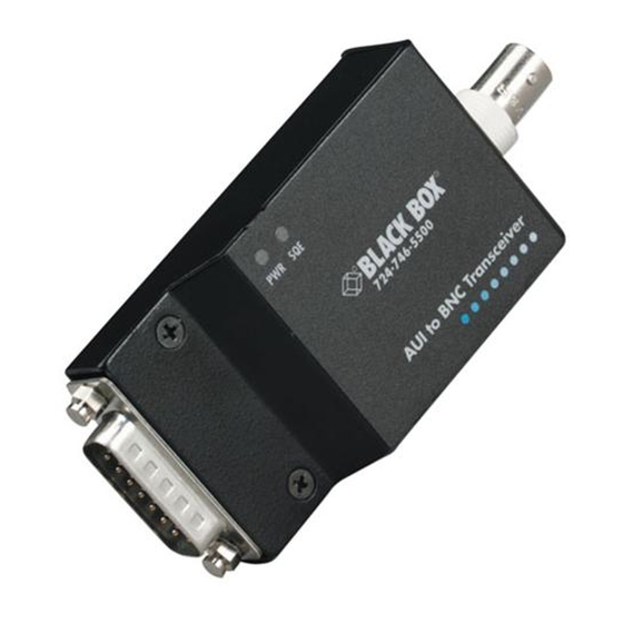
CHAPTER 2: Introduction 2. Introduction 2.1 Description The AUI to BNC Transceiver lets you connect an Ethernet device (such as a LAN card installed in a PC, or a bridge, router, hub, or repeater) to thin Ethernet coaxial cable. It connects either directly to the AUI port on the Ethernet device or via a standard AUI cable. -
Page 11: Features
AUI TO BNC TRANSCEIVER • (1) BNC T-connector • This users’ manual If anything is missing or damaged, please contact Black Box at 724-746-5500. 2.3 Features • Provides a complete AUI to thin Ethernet (10BASE2) interface, including transmit, receive, collision, and jabber functions, and SQE (signal quality error) test. - Page 12 CHAPTER 2: Introduction • Supports system configurations using the CSMA/CD access mechanism defined in the IEEE Local Area Network specifications.
-
Page 13: Installation
AUI TO BNC TRANSCEIVER 3. Installation 3.1 Disabling SQE Test When the transceiver is attached to a LAN card, bridge, or router, the SQE switch (located on the bottom of the transceiver) should be ON. When the transceiver is attached to a hub or repeater, the SQE switch should be OFF. -
Page 14: Installing The Transceiver
CHAPTER 3: Installation 3.2 Installing the Transceiver 1. Turn the power to the network device off. 2. Connect a BNC T-connector to the transceiver’s BNC female connector, then connect thin coax cable to the T-connector. If only one end of the T-connector is connected, install a 50-ohm BNC terminator on the other end. - Page 15 AUI TO BNC TRANSCEIVER Once the transceiver is installed, it operates automatically in half-duplex mode. When the SQE LED lights, a collision is detected on the AUI port.
-
Page 16: Troubleshooting
CHAPTER 4: Troubleshooting 4. Troubleshooting 4.1 Calling Black Box If you determine that your AUI to BNC Transceiver is malfunctioning, do not attempt to alter or repair the unit. It contains no user-serviceable parts. Contact Black Box at 724-746-5500. Before you do, make a record of the history of the problem. -
Page 17: Shipping And Packaging
• Package it carefully. We recommend that you use the original container. • If you are shipping the transceiver for repair, make sure you include everything that came in the original package. Before you ship, contact Black Box to get a Return Authorization (RA) number. -
Page 18: Appendix. Aui (Db15) Connector
APPENDIX: AUI (DB15) Connector Pinout Appendix. AUI (DB15) Connector Pinout Symbol Name/Function CI-S Control-In Shield: The shield for the CI twisted pair in the AUI cable. CI-A Control-In Circuit A: The positive signal for the CI circuit. With CI-B, CI-A is an output current driver pair to the CI circuit. - Page 19 AUI TO BNC TRANSCEIVER Symbol Name/Function DO-A Data-Out Circuit A: The positive signal for the DO circuit. With DO-B, DO-A is a differential receiver input pair from the DO circuit. This input pair receives 10-Mbps Manchester- encoded data from the AUI transceiver cable, which is driven by the DTE (terminal or computer).
- Page 20 APPENDIX: AUI (DB15) Connector Pinout Symbol Name/Function CI-B Control-In Circuit B: The negative signal for the CI circuit. With CI-A, CI-B is an output current driver pair to the CI circuit. This output pair is activated when a collision is detected on the network, either during self-test (heartbeat) as the SQE test sequence or after the watchdog timer...
- Page 21 AUI TO BNC TRANSCEIVER Symbol Name/Function DI-B Data-In Circuit B: The negative signal for the DI circuit. With DI-A, DI-B is an output current driver pair to the DI circuit. This output pair drives the AUI transceiver cable with 10-Mbps Manchester-encoded data received from the coaxial cable wire of the network.
Need help?
Do you have a question about the LE1601A and is the answer not in the manual?
Questions and answers