
Related Manuals for Data Flow Systems TCU800


Summary of Contents for Data Flow Systems TCU800
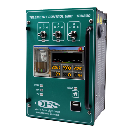
- Page 1 Data Flow Systems, Inc. P r e l i m i n a r y Installation and Operation Manual T C U 8 0 0...
- Page 2 Intentionally left blank.
- Page 3 TCU is utilized in a DFS TAC II SCADA System. These special features and functions may not be available when the TCU800 is utilized in a 3rd party SCADA System. If you are unsure about the availability of a feature or function, please contact DFS for clarification.
- Page 4 D a t a F l o w S y s t e m s , I n c . Intentionally left blank.
-
Page 5: Table Of Contents
T C U 8 0 0 U s e r M a n u a l Contents Preface Purpose of this Manual........................................iii Document Conventions........................................iii Abbreviations Used in this Manual....................................iii 1. Safety Precautions General Precautions..........................................1 Connecting/Disconnecting the TCU....................................1 Protecting against Electrostatic Discharge..................................1 2. - Page 6 MODBUS............................................58 Derived Flow............................................59 TCU Settings............................................59 Radio Test Mode..........................................60 Reset Pump Stats..........................................61 Time..............................................61 Auto Configuration...........................................61 Device Manager..........................................62 Calibrate PMA..........................................62 Factory Reset............................................62 Telemetry Configuration........................................64 7. Viewing and Troubleshooting Alarms AC Power Fault..........................................69 Auxiliary Input Alarm ........................................70 DC Bias Fault...........................................70 Float Sequence Fault........................................71 High Well Alarm..........................................71 Phase Sequence Fault........................................71 Phase Voltage Fault...........................................72...
- Page 7 I. TCU Transducer Configuration Examples 4-20 mA or 0-5 VDC Transducer with High Float (Pump Down Mode).........................114 4-20 mA or 0-5 VDC Transducer with Floats Backup (Pump Down Mode)........................116 4-20 mA or 0-5 VDC Transducer with Analog Input 2 as Backup (Pump Down Mode)....................119 Discrete System (Pump Down Mode)....................................121 J.
- Page 8 Intentionally left blank.
-
Page 9: Preface
Preface Purpose of this Manual This manual is a reference guide for installing and operating the TCU800 (Telemetry Control Unit). It contains information meant to guide and assist in the installation and configuration procedure. This includes mounting and wiring instructions, product features and specifications, I/O listings, instructions for integrating with telemetry, information on Modbus compatibility, and instructions for configuring and using the TCU’s pump control process. - Page 10 Intentionally left blank.
-
Page 11: Safety Precautions
D a t a F l o w S y s t e m s , I n c . 1. Safety Precautions Review the following information before installing, servicing, or replacing the TCU or any of its components. General Precautions •... -
Page 12: Product Overview
C h a p t e r 2 2. Product Overview Description The TCU800 is a highly integrated pump controller running an embedded Linux operating system. It is designed to be backward compatible with its predecessor (TCU001) while including additional feature enhancements to expand its operability. -
Page 13: Features
P r o d u c t O v e r v i e w control and monitor the six onboard digital outputs, 18 digital inputs and four analog inputs. It also features an expansion card slot which can be used to add additional I/O points for specialized applications, such as controlling VFD pumps. Features True RMS AC phase monitor produces voltage readings for single- and three-phase True RMS AC Phase Monitor... -
Page 14: Compatibility
4 Analog Inputs for well level and auxiliary measurement Compatibility Please note that the PCU, PCU TAC Pack, SCU, and SCU TAC Pack are not “upward” compatible with the TCU800. DFS’ Sales Department can provide assistance with ensuring that your system has appropriate replacement units on hand. -
Page 15: Pin Names/Wiring Definitions
Autodialler - no longer available By default, the TCU800’s new digital and analog inputs are disabled so as not to conflict with any pre-configured MODBUS devices that may be occupying modules H through O. In order to enable the new I/O, which will be dynamically assigned at the next available module space, see procedure on page 82. - Page 16 C h a p t e r 2 P1-10 BEMGND Isolated ground (wire to BEM001, pin 12) <24V / Not Rated P1-11 BEM_PWR Isolated power (wire to BEM001, pin 10) <24V / Not Rated P1-12 BEM_CTS Isolated clear to send (wire BEM001, pin 6) <24V / Not Rated P1-13 BEM_RXD Isolated receive data (wire to BEM001, pin 4)
- Page 17 P r o d u c t O v e r v i e w P3-12 SHUNT 250Ω shunt resistor; jump to P3-11 to use a 4-20mA <24V / Not Rated signal for ANALOG4+ (P3-10) P3-13 SHIELD Internally connected to chassis ground; cable shield Ground for analog monitor signals P3-14 IN_COM_3...
- Page 18 C h a p t e r 2 P2-20 SHIELD Internally connected to chassis ground; cable shield for Ground analog monitor signals P2-21 ANALOG2+ 4-20 mA signal from transducer; - signal at pin P2-23; <24V / Not Rated internal 250Ω shunt permanently connected P2-22 ANALOG1+ 0-5VDC or 0-10VDC or 4-20 mA signal from trans- <24V / Not Rated...
-
Page 19: Unit Overview
The following sections describe what the available features of the TCU800 are and how they monitor and operate various parts of the pump control systems. The descriptions are from the perspective of the TCU800 as a unit interacting with a pump control system. -
Page 20: Hand-Off-Auto (Hoa) Switches
Soft Touch Button The TCU800 has a single soft touch button labeled with a home symbol. The button is located on the right side of the face- plate, below the Alarm LED and above the USB ports. The purposes of the button are as follows: to power the unit on or off, to wake up the display, to return to the home screen, and to acknowledge alarms to prevent the alarm horn sounding. -
Page 21: Usb Ports
A congifuration USB can be placed in either of the two USB ports. Boot-Up: When the TCU800 boots up, it checks for a USB with a configuration, loads it, and saves it internally. If no con- figuration USB drive is available or the USB drive has failed, the TCU800 will use the last stored configuration. -
Page 22: Monitoring And Control
External Phase Monitor: The external phase monitor input is provided as both an internal bypass and an alarm input. The purpose of this input is to allow a system to use either the TCU800’s phase monitoring system or an external phase monitor whose alarming condition is passed through the TCU800’s alarms. -
Page 23: Digital Output Control
U n i t O v e r v i e w of the TCU800’s alarm system. The input is normally held high with no phase voltage fault. When an alarming condition occurs on the external monitoring system, bringing the input low will cause an alarm on the TCU800. -
Page 24: Serial Connectivity
RS-232 clear to send Phase Voltage Monitoring The TCU800 has an internal system to monitor phase voltages and provide fault detection for several faults. The TCU800’s internal phase monitoring can also be bypassed and an external phase monitor can be used. -
Page 25: Internal Monitoring
Internal Temperature Internal temperature monitors the TCU800’s temperature. AC Power Fault AC Power fault is provided when no AC power is applied to the unit. This will only be available when the TCU800 is on battery backup. DC Bias Fault The DC Bias fault is active when the 24VDC bias power supply drops below 20VDC. -
Page 26: Level Sensing Transducers
C h a p t e r 3 Telemetry Interface Connecting to a telemetry system provides the ability to remotely control the individually pumps with two software switches: Override – (when tuned on) remotely forces a pump On, and Disable - (when tuned on) remotely forces a pump Off, and effectively disables the the TCU from automatically controlling a pump. -
Page 27: Outputs
A USB flash drive correctly formatted and loaded with appropriate files will allow easy transfer of pump configuration parameters from one TCU to another. The TAC Pack TCU Configuration Connector or address card is not used in the TCU800. Instead, the USB configuration stick will replace this method of setting the TCU’s station address. -
Page 28: Electrical Protection
C h a p t e r 3 The menus on the home screen are listed below. Trend View Displays float level and time period history (configurable). Quick View Displays the status of 12 inputs from the original TCU and 6 outputs. Digital Inputs Displays the status of all 16 digital inputs. -
Page 29: Principles Of Operation
U n i t O v e r v i e w Principles of Operation Simplex, Duplex, and Triplex Stations The station type is determined by the number of pumps at the station. A simplex station consists of one pump. At a minimum, a simplex station uses the Off and Lead staging Simplex levels. - Page 30 C h a p t e r 3 alarm is issued and normal pump control is overridden. Note: If the Low float is not going to be used, it must be disabled in the TCU’s local configuration for the TCU’s pump control operations to function normally in automatic.
-
Page 31: Analog System (Pressure Transducer)
U n i t O v e r v i e w Minimum operational level of a tank. All pumps are stopped when the tank’s Off Level level is above the Off level. Lead (first) pump is started. Lead is active when the tank’s level is below the Lead Level Lead level. - Page 32 C h a p t e r 3 Note: If the Low float is not going to be used, it must be disabled in the TCU’s local configuration for the TCU’s pump control operations to function normally in automatic. Failing to disable the Low float configuration in this situation, results in a false alarm condition, which fails the transducer.
- Page 33 U n i t O v e r v i e w Lead Off is the maximum operational level of a tank. Lead pump is stopped Lead Off Level when the well’s level is above the Lead Off level. Lag Off Level (duplex and triplex Lag (second) pump is stopped.
- Page 34 C h a p t e r 3 The TCU uses a numeric alternation scheme. With numeric alternation, the pump assigned as the new Lead pump is always the next in the numeric order. For example, in a triplex lift station, if pump 2 (current Lead pump) and pump 3 (current Lag pump) are running when the Lead Off level is reached, pump 3 would become the new Lead pump regardless of the number of pumps running.
- Page 35 U n i t O v e r v i e w 3. Tries the next pump The preferred method for monitoring motor run is to use phase A at the load side of the motor breaker as motor run bias, and feed the bias through the starter auxiliary contacts to the TCU’s motor run input terminal with a proper bias resistor in the circuit.
- Page 36 C h a p t e r 3 disabled from the TCU’s local configuration. All conditions that activate the alarm horn and alarm light are reported through the telemetry system. Alarm outputs are activated only when the TCU detects an alarm condition, such as phase faults, high and low-well conditions, and internal TCU faults.
-
Page 37: Setup
S e t u p 4. Setup Mounting Instructions The TCU is intended to be permanently installed in a NEMA 12 or higher rated panel that prevents access to live parts with- out a tool. The TCU can be mounted in a control panel in several different ways. The unit can be mounted flush to the back plate of the panel, stood off the back plate, or mounted to a front panel. -
Page 38: Electrical Installation And Wiring Diagrams
C h a p t e r 4 Electrical Installation and Wiring Diagrams The electrical interface to the TCU is broken down into several groups of signals. The wiring of each group is detailed in the following paragraphs. These instructions are written specifically for a TCU using the built-in pump control process. Although many of them apply to custom applications as well, the Applications Engineer will be primarily responsible for defining and implementing the TCU’s inputs and outputs. - Page 39 S e t u p Wiring AC Power (typical 240 V, 4-wire transformer) Wiring AC Power (typical 480 V, 3-wire transformer) Motor Starter Outputs 1. Connect control power to the STR_PWR terminal (P1-24). 2. Connect the MTR1_STR terminal (P1-23) through a 1 A slow-blow fuse to the coil of the motor starter or the control relay designated as Pump 1.
- Page 40 C h a p t e r 4 Simplex stations use only MTR1_STR. Duplex stations use MTR1_STR and MTR2_STR. Triplex stations use all of the motor starter outputs. Unused starter outputs can be used as auxiliary outputs with control provided by telemetry. Motor Starter Circuit Wiring Alarm Light and Horn Outputs The alarm outputs use mechanical relays to drive up to 0.5 A at 120 VAC or 1 A at 0-24 VDC.
- Page 41 S e t u p Using Snubbers When Connecting Alarm Outputs For AC applications, we recommend an RC snubber (DFS # 007-0084) using a 0.1uF capacitor in series with a 47 Ω ½ W resistor, such as that manufactured by RED LION (Model # SNUB0000). Snubber in AC Alarm Output Application For DC applications, we recommend a power diode (DFS # 006-0019) with a minimum 3 A 100 peak inverse voltage (PIV) fast acting rating, such as the industry standard 1N4004 (DIGIKEY # 1N4004CT-ND).
- Page 42 C h a p t e r 4 Single-Phase Monitor Wiring Three Phase Option Connections to the three-phase lines are used for monitoring phase sequence and voltage levels of the incoming power. The TCU’s phase monitor is labeled for clockwise phase sequence. If the three-phase power is labeled for counter-clockwise rotation and is connected in accordance to the TCU’s terminal label, the TCU will detect a phase sequence fault.
-
Page 43: Bias Voltage Source Options
S e t u p Digital Monitor Point Inputs The TCU has 18 digital monitor point inputs. These monitor points require an input and a return. All digital inputs support 10-30VAC/DC or 30-300VAC with external resistors. Note that the auxiliary input (P2-12) supports pulse input capture instead of VAC. - Page 44 C h a p t e r 4 Externally-Supplied Bias Voltage Source Externally supplied bias voltages can be used to bias the inputs. If the voltage is greater than 30 VAC/VDC, a voltage- dropping resistor must be placed in line with the input. A minimum voltage of 10 VAC/VDC is required to indicate an ON state for the digital monitor inputs.
- Page 45 S e t u p Input Bias Voltage Resistor Size BIAS + None 10-30 VDC/VAC None 31-100 VDC/VAC 22K, 1/2 W 101-200 VDC/VAC 47K, 1/2 W 201-300 VDC/VAC 100K, 1 W Motor Run Monitoring Signal (4-wire transfer)
- Page 46 C h a p t e r 4 Motor Run Monitoring Signal (3-wire transformer) Level Sensing Transducers A TCU using the pump control process can accommodate two different types of input-supported transducers. • Digital-type devices such as contact closures, float switches, and pressure switches •...
- Page 47 S e t u p These six inputs, plus the AUX_IN (P2-12) and ALM_SIL (P2-13) inputs, are internally connected to IN_COM_2 (P2-14). All eight of these inputs must be biased with the same voltage source. Simplex stations use input terminals LOW_LVL (P2-6), OFF_LVL (P2-7), LEAD_LVL (P2-8), and HIGH_LVL (P2-11). Duplex stations add input LAG1_LVL (P2-9).
- Page 48 C h a p t e r 4 Input commons on the TCU must be either AC neutral (with no voltage potential when referenced to earth ground) or the negative terminal of a DC power supply. Analog Level Transducer The terminals for the analog interface are: •...
- Page 49 S e t u p TCU Powered Non-submersible Transducer Externally Powered Non-submersible Transducer...
- Page 50 C h a p t e r 4 Auxiliary Analog Input The TCU’s secondary analog input can be used as a backup to the primary analog level transducer or can be used for a general purpose analog input (for example, a flow transducer). For more information on using analog input 2 as a backup to the primary transducer, see “Transducer Fault Mode”...
- Page 51 S e t u p connecting the backup battery, since this circuit is not diode protected. Alarm Silence Switch The alarm horn, if installed, can be silenced in three ways: through the ALM_SIL input, by pressing the TCU’s Power/ Home button, or by navigating to the TCU’s Alarm screen and viewing the alarm. The following describes the wiring of a momentary alarm silence switch.
- Page 52 C h a p t e r 4 External Phase Monitor Phase Monitor Bypass The TCU’s internal phase monitor can be bypassed (i.e., disabled) if it is not required. To bypass the TCU’s phase monitor, connect a bias voltage (through a voltage-dropping resistor if required) directly into the EXT_PM terminal (P2-4). Use the same bias voltage source that was used to bias the motor run (MTRx_RUN) inputs (P2-1, P2-2, P2-3).
- Page 53 S e t u p Phase Monitor Bypass Auxiliary Input and Output Connections The TCU provides an auxiliary digital input and output that can be configured together to function as an auxiliary relay. The AUX_IN terminal (P2-12) functions as one side of a relay coil and the IN_COM_2 terminal (P2-14) as the other. The AUX_PWR terminal (P1-18) and AUX_OUT terminal (P1-19) function as contacts for the relay.
-
Page 54: Installed In Rtu
C h a p t e r 4 Auxiliary Digital Output Installed in RTU When a TCU is included in an RTU via a BEM, it is important to remember that the TCU defines its internal modules without exception. Any additional modules added to the RTU must be addressed beginning with the module letter after the last dummy module defined in the TCU. -
Page 55: User Interface
U s e r I n t e r f a c e 5. User Interface HOA switches HOA LEDs touchscreen status LED receive LED soft touch button transmit LED USB port ethernet pigtail (optional) radio pigtail (optional) Trend View... - Page 56 C h a p t e r 5 Quick View Analog View Pump Statistics...
- Page 57 U s e r I n t e r f a c e Alarms Settings, Screen 1 Settings, Screen 2...
- Page 58 C h a p t e r 5 Advanced Settings About...
-
Page 59: Operating Procedures
Configuration Setup Configuring the TCU800 is done from the Settings screen. First, ensure the H-O-A switches are all in the HAND or OFF position. Then navigate to the Settings screen by tapping the screen, opening the left Navigation Menu by tapping scroll down using an upward swipe, and tap to select Settings. - Page 60 TCU800 to the remote PLC editor (once). If taking this step, disregard the configuration values listed in the Autodialer section of the editor as the TCU800 does not support Autodialer and the settings have been re-purposed for other use. This workaround is temporary.
-
Page 61: Main Settings
O p e r a t i n g P r o c e d u r e s Main Settings Options under the Main Settings Menu are used to configure the main functions of the unit, such as the number of pumps, the pump mode, transducer type, and alternator type. -
Page 62: Alarm Outputs
C h a p t e r 6 The TCU can be configured to retry a faulted pump - one that fails to start when called (Motor Start Fault) or one that is running when it has not being called to run Auto Retry (Motor Stop Fault). -
Page 63: Radio
Off float failure when the TCU is in Float control mode (this can be a floats-only Enabled) system or an analog transducer system that uses floats for backup). Radio Options under the Radio Menu are used to configure the TCU800’s station address and radio protocol settings. - Page 64 C h a p t e r 6 Station The number assigned to the pump station. Data Invert and Data Swap are used to prevent cross-talk from other DFS radio Data Invert systems on the same frequency. Although uncommon, atmospheric conditions can occur that allow low power transmitters to ‘skip’...
-
Page 65: Auxiliary
O p e r a t i n g P r o c e d u r e s Auxiliary Options under the Auxiliary Menu are used to configure the auxiliary input, auxiliary output, and time delay relay. Together, the settings AuxOut Turns (On/Off) and AuxIn Turns (On/Off) define how AUX_OUT responds when the state of AUX_IN changes. -
Page 66: Analog
C h a p t e r 6 Analog Options under the Analog menu are used to configure the pump settings to adhere to the physical measurements of a particular well. • Pump Up mode – In tank filling operations, the TCU stops all three pumps and activates alarms when the tank’s level rises above this set point. -
Page 67: Phase Monitoring
O p e r a t i n g P r o c e d u r e s • Pump Up mode – In tank filling operations, the TCU starts the Lead, or first, pump when the tank’s level falls below this set point. Lead On Level •... -
Page 68: Pump Monitoring
C h a p t e r 6 Pump Monitoring Options under the Pump Monitoring Menu are used to control the Thermal and Seal Failure functionality as well as the Auxiliary Analog settings. Select this option to enable the new (extended) digital inputs (Seal Fail/Therm Digital Module Fail) on P3. -
Page 69: Modbus
Raw Low and High. Modbus Options under the Modbus Menu are used to configure additional Modbus devices connected to the TCU800. After all of the information for Modbus slave devices has been entered, enter the Protocol protocol, bit number, and parity for the devices being polled by the TCU. -
Page 70: Derived Flow
Subnet the default value (255.255.255.0) if not required. Domain Name System If the TCU800-IP is operating through a gateway, the gateway’s full IP address Gateway must be entered here. Options for home screen designs displaying a range of data on the pump (Trend Home Screen View, Quick View, Analog View, Statistical View, Graphical View, System Health). -
Page 71: Radio Test Mode
Auto-Configuring At this time, using a TCU001 PLC configuration will cause an error in the TCU800. To avoid this, first transfer the existing configuration of the TCU800 using HyperTAC PLC editor. Then save the .plc file, create an auto-config file, and upload it to the appropriate station you want to auto-config. -
Page 72: Reset Pump Stats
C h a p t e r 6 Reset Pump Stats Selecting the Reset Pump Statistics option displays a prompt confirming a reset of the pump statistics since the last reset. If ‘Yes’ is selected, the statistics will be reset. If ‘No’ is selected, the pop up will clear and the screen will return to the Advanced Settings menu. -
Page 73: Device Manager
O p e r a t i n g P r o c e d u r e s Device Manager Selecting “Export Settings” will export the current TCU configuration to the USB drive currently inserted in the top drive. After this is done, a message prompt will appear confirming the export was successful. -
Page 74: Telemetry Configuration
C h a p t e r 6 Telemetry Configuration Setting up the TCU as a component of the telemetry system enables you to remotely monitor conditions at the site and control equipment from a central location via the HyperTAC SCADA software. For example, you can determine if a pump is currently running and force it on if necessary. - Page 75 O p e r a t i n g P r o c e d u r e s Make the following connections: Description P1-2 Telemetry TX P1-14 P1-4 Telemetry RX P1-13 P1-6 Telemetry CTS P1-12 P1-8 Telemetry RTS P1-15 P1-10 Telemetry PWR P1-11...
- Page 76 C h a p t e r 6 PIN# Name Description P4-1 Unused Reserved for future use; do not connect P4-2 RS485_GND RS-485 serial ground reference P4-3 RS485_B RS-485 serial interface B P4-4 RS485_A RS-485 serial inferface A P4-5 SHIELD Internally connected to chassis ground;...
- Page 77 O p e r a t i n g P r o c e d u r e s TCU Installed in Existing Control Panel...
- Page 78 C h a p t e r 6 TCU Installed in Separate Control Panel TCU Used without Telemetry The TCU can operate independent of telemetry with limited data logging capabilities. Historical data can be accessed via WinRTU Test or the TCU’s status screens. Historical data that can be reviewed includes: - Derived total flow for the station - Elapsed run time for each configured pump - Average run time for each configured pump...
-
Page 79: Viewing And Troubleshooting Alarms
V i e w i n g a n d T r o u b l e s h o o t i n g A l a r m s 7. Viewing and Troubleshooting Alarms The information contained in this chapter refers to the TCU’s built-in pump control process. It does not apply to a TCU with a custom program installed. -
Page 80: Auxiliary Input Alarm
C h a p t e r 7 If an AC power fault alarm occurs at a TCU that is connected to a backup battery: • Check that all circuit breakers are on. • Check if any circuit breaker has tripped. If a station control panel breaker has tripped, resolve the problem. •... -
Page 81: Float Sequence Fault
V i e w i n g a n d T r o u b l e s h o o t i n g A l a r m s When a float sequence fault alarm occurs: • Check the floats or pressure switches for the fault. Verify that the corresponding Well Level LED illuminates when each float or pressure switch is on. -
Page 82: Phase Voltage Fault
C h a p t e r 7 Phase Voltage Fault The TCU’s phase monitor is designed to detect phase losses, high-and low-phase voltage faults and phase sequence faults. When the TCU detects a phase fault, it disables the pump motor outputs and activates the alarm light and horn relays. The H-O-A switches can be used to override the TCU’s phase monitor and control the pumps during a phase fault. -
Page 83: Motor Stop Fault
V i e w i n g a n d T r o u b l e s h o o t i n g A l a r m s Check the starter circuit for faults by using the H-O-A switches to control the pumps. Verify that the pump run LED and the corresponding pump motor turn on when the H-O-A switch is in the “Hand”... -
Page 84: Transducer Fault
C h a p t e r 7 • The mechanical auxiliary contacts on the motor controller’s starter contactor are functioning properly. If they have been damaged and are stuck in the closed position, the motor controller will not receive the pump stop signal. •... -
Page 85: Leaving The Alarms Screen
V i e w i n g a n d T r o u b l e s h o o t i n g A l a r m s If the transducer is determined to be functional, the TCU may require factory service. See “Appendix H: Support, Service, and Warranty”... -
Page 86: Modbus Support
C h a p t e r 8 8. Modbus Support Modbus Support The TCU provides support for Modbus slave and master devices via its RS-232 and RS-485 serial interfaces. Note that the TCU can be used as both simultaneously. For example, it could respond to queries from a Modbus master HMI software package (via RS-232) while querying DIN-rail mounted RS-485 slave devices. - Page 87 M o d b u s S u p p o r t Figure 1 Figure 2 Figure 3...
- Page 88 C h a p t e r 8 Do not use the TCU to power an external RS-232 Modbus-compatible device (for example, a radio, modem, or PLC). The device must be powered by a source other than the TCU. Wiring External Modbus-compatible RS-232 Device The TCU’s P-4 connector provides pins for connecting the TCU to an external RS-232 Modbus compatible device (see table below for pin descriptions for connector P-4).
- Page 89 M o d b u s S u p p o r t Configuring Modbus Device ID The valid device ID range for the TCU is 1-250. TCU Radio System Setup Radio communication requires that the TCU be installed in a location, preferably a control panel, with access to an antenna. This illustration provides details on grounding a TCU that is installed in a control panel.
- Page 90 C h a p t e r 8 The TCU does not support: Force Multiple Coils (control multiple control registers) Preset Multiple Registers (control multiple analog control registers) TCU as a Modbus Master Device (RS-485 Interface When the TCU is used as a fixed-speed pump controller, it can poll modbus slave devices and place their register data in the TCU’s unused registers.
- Page 91 M o d b u s S u p p o r t Figure 7 Configuring the TCU to Poll Modbus Slave Pump Control Process When using the TCU as a fixed-speed pump controller, you configure the TCU to poll Modbus slave devices using one of the following methods: •...
-
Page 92: Appendix
D a t a F l o w S y s t e m s , I n c . Appendix... -
Page 93: Technical Specifications
T e c h n i c a l S p e c i f i c a t i o n s A. Technical Specifications Box Dimensions 5.75” x 8.75” x 5.45” Supply Voltage 120VAC +/-10%, 60Hz Supply Current 0.5-1.5A Processor Core AM335x SoC, 512MB of memory and 1GHz... -
Page 94: Checkout Procedure For Pump Controller
A p p e n d i x B B. Checkout Procedure for Pump Controller Step 1: Electrical Termination Review NEC code and OSHA safety standards should be observed during all installation, grounding and testing procedures. Modifications to the following should be made as necessary to stay within NEC and OSHA guidelines. Confirm with DFS regarding proper procedure if the following becomes obsolete due to code or regulation changes. -
Page 95: Step 2: Operations Testing
C h e c k o u t P r o c e d u r e f o r P u m p C o n t r o l l e r 10. Verify that the proper fuses are installed in the output circuits of the motor starter, alarm light and horn, and auxiliary. 11. - Page 96 A p p e n d i x B 11. Verify, as the LAG1 and LAG2 inputs are toggled, that the TCU starts additional pumps that the level input demands. Allow for some delay on pump start after the level input is activated. 12.
-
Page 97: Maintenance And Troubleshooting
Blown Fuse The TCU800 includes one 2A replaceable fuse. The fuse is located on the side of the TCU and is labled F601. The fuse is designed to protect the TCU’s DC power circuitry from its operating AC input voltage. -
Page 98: Tcu Replacement
A p p e n d i x C 1. Before removing the TCU, either make a note of the TCU configuration or download the configuration to a computer.* 2. Turn off all circuit breakers before attempting to remove the TCU. 3. -
Page 99: Parts List
P a r t s L i s t D. Parts List Furnished Parts TAC Pack Telemetry Control Unit (TCU) DFS-00540-008-01(NO RADIO) DFS-00540-008-16 (IP) DFS-00540-008-21 (145-225 MHZ RADIO) DFS-00540-008-22 (450-470 MHZ RADIO) DFS-00540-008-26 (LEGACY XT200 RADIO) Optional Parts Batteries 12V, 7.0Ah Rechargable Battery 12V, 2.6Ah Rechargable Battery Part #DFS-00363-008-01 Part #DFS-00363-008-02... - Page 100 A p p e n d i x D Network Surge protection for Rail Pressure Transducer (RPT) 1000/100/10-Base-T Small Parts Kit Part #DFS-002-0584 Part # DFS-00546-008-02 Bus Extender Module Circuit Breaker Part #DFS-00223-008-01 Part #014-0010...
- Page 101 P a r t s L i s t Adjustable Mounting Bracket (Short) Part #DFS-00394-008-01 1A Slow Blow Fuse Part #DFS-00271-008-09 TCU Snap in Install Kit Part #DFS-00392-008-09...
- Page 102 A p p e n d i x D TCU Front Mount Install Kit Part #DFS-00392-008-05 Adjustable Mounting Bracket (Medium) Adjustable Mounting Bracket (Long) Part #DFS-00394-008-02 Part #DFS-00394-008-03...
- Page 103 P a r t s L i s t 480 VAC Phase Monitor Kit Adjustable Mounting Bracket (Long) Part #DFS-00393-008-05 Part #DFS-00394-008-03 (Kit includes 480 VAC, three-phase surge arres- tor, three DIN-rail mounted terminal blocks with integrated 49.9k resistors, and fuse block with three 1 Amp fuses) Power Diode 47K Resistor (Part #DFS-00271-008-01)
- Page 104 A p p e n d i x D Service Adapter RC Snubber Part #002-0540 Part #007-0084 120V Surge Protector (SPS001) 240V Surge Protector (TPS001) Part #DFS-005-0061 Part # DFS-005-0062...
- Page 105 P a r t s L i s t USB Thumb Drive Part # DFS-00540-108-06 USB to RS-232 Adapter Part #002-0351 Spring-Clamp Connector Tool Part #DFS-00389-008-01...
-
Page 106: Mounting Instructions
A p p e n d i x E E. Mounting Instructions The TCU is intended to be permanently installed in a NEMA 12 or higher rated panel that prevents access to live parts without a tool. The TCU can be mounted in a control panel in several different ways. The unit can be mounted flush to the back plate of the panel, stood off the back plate, or mounted to a front panel. - Page 107 M o u n t i n g I n s t r u c t i o n s Snap-In (Back Panel) Mount The mounting bracket is attached to the back of the control panel, and the TCU is snapped into place. With this mounting option, the TCU can be installed and removed quickly and easily.
- Page 108 A p p e n d i x E TCU Front Panel Mount With this mounting option, the TCU is attached to the mounting bracket with screws instead of being snapped into place. This option uses the Front Mount installation kit (Basic Install Kit or Full Install Kit). See “Appendix D: Parts List.”...
- Page 109 M o u n t i n g I n s t r u c t i o n s The graphic below depicts how each of the TCU’s three optional connector types can be attached to the unit. The first option uses the Spring-Clamp Connector Tool.
- Page 110 A p p e n d i x E A dimensional drawing is provided to aid in installation. If a panel cutout is required, the TCU can be installed with or without edge molding around the front-panel opening. The panel cutout is different for each mounting configuration.
-
Page 111: Well Volume Calculations
W e l l V o l u m e C a l c u l a t i o n s F. Well Volume Calculations To calculate Well Volume, determine the well volume between the Off Level (LeadOff Pt) and the Lead Level (LeadOn Pt). 1. -
Page 112: Adding A Rio To The Tcu
A p p e n d i x G G. Adding a RIO to the TCU The TCU can poll Modbus slave devices, such as the RIO032 and RIO128, and store their data in the TCU’s unused modules (referred to as modules H-O in the TCU’s configuration screen). This information can then be made available to your telemetry system by adding and configuring the modules in HT3. -
Page 113: Configure Rio For Learn Mode
A d d i n g a R I O t o t h e T C U The device/station address is configured by turning off switch positions that add up to the desired station number. Each bit (pin on the separate address board – P6-1 through P6-8) has a corresponding value (see table below). The RIO032 is set to a specific device/station address by leaving particular pins on the address board’s DIP switch ungrounded, or in the Off position. -
Page 114: Mount Rio And Wire Ac Power And I/O
A p p e n d i x G Mount RIO and I/O Refer to the RIO032 Installation and Operation Manual for detailed instructions. • Chapter 4: Mounting the RIO032 • Chapter 5: Electrical Installation Connect RIO to TCU The TCU’s RS-485 interface is located on the TCU’s P4 connector. Pin definitions for the TCU, RIO032, and RIO128 RS- 485 interfaces appear below followed by a wiring diagram. -
Page 115: Place The Rio In Learn Mode
A d d i n g a R I O t o t h e T C U Place the RIO in Learn Mode When all of the RIO’s communication configuration switches are left in the Off position (see step 2, Configure RIO for Learn Mode, above) and the RIO’s configuration button is held down during power up, the RIO enters learn mode. -
Page 116: Verify Communication Between Tcu And Rio
A p p e n d i x G • Address is the RIO’s device number and the first of the range of registers being added to the current module. For example, ModH Adr would be 1.10001 when adding digital inputs to device 1, module H. •... - Page 117 A d d i n g a R I O t o t h e T C U For a RIO032 using all 32 I/O points, add the following: Module Letter Module Type (Number of I/O Points) Module H DMM (8 digital input points) Module I DCM (8 digital output points) Module J...
-
Page 118: Ct Module
Installing CTs 1. CTs will be mounted in a separate panel (where the 3 phase main breaker is located) from the TCU800. 2. CTs will be attached to the lines after the main breaker but before the individual pump starters. - Page 119 C T M o d u l e Configuration All configuration settings are located in the “PMA Settings” of the TCU800’s “Settings” menu. Configuration Description Options Default CT Module Enables or disables the new CT features of Enabled/ Disabled Disabled the TCU800.
- Page 120 A p p e n d i x H CT Rating The maximum current the CTs will read when 5 - 100 outputting 333 mVAC. If the CTs being used do not output 333mVAC at full scale, they can either not be used or a calculation must be done to determine what the current would be at 333mVAC.
- Page 121 C T M o d u l e Installing CTs CT Function = Motor Currents 1. Pump Number and Run Indicator 2. Average Current while the pump is RUNNING* 3. Average phase imbalance exhibited while the pump is RUNNING** 4. 3-Phase voltage (smoothed realtime) 5.
- Page 122 A p p e n d i x H CT Function = Direct Input 1. 3-Phase current imbalance (smoothed realtime) 2. Average current (smoothed realtime) 3. Minimum current measured in the last 24 hours 4. Maximum current measured in the last 24 hours Alarms None of the faults triggered from this module interrupt the pump control operation - they are warnings only (sent via telemetrey) and notice on GUI.
- Page 123 C T M o d u l e Amp 3 Fault Triggers when the AMPS reading goes above Set FLC 2 = 0 the overcurrent limit (% of FLC 3) or below the undercurrent limit (% of FLC 3). Phase Current Fault Generic fault that indicate other misc.
-
Page 124: Tcu Transducer Configuration Examples
A p p e n d i x I I. TCU Transducer Configuration Examples The examples in this appendix are the most typical applications and can be used as a guide for configuring your system to obtain the pump control and fault mode behavior required. Note: The examples provided here are for systems in “pump down”... - Page 125 T C U T r a n s d u c e r C o n f i g u r a t i o n E x a m p l e s Transducer Low Level Fault Enabled Enable to generate a transducer page 54 fault when a low float condition occurs.
-
Page 126: Ma Or 0-5 Vdc Transducer With Floats Backup (Pump Down Mode)
A p p e n d i x I Concurrent • Transducer All pumps on Low well, high well, and transducer fault transducer low fault alarm alarms are generated. High float condition takes and high float precedence over the transducer low condition and •... - Page 127 T C U T r a n s d u c e r C o n f i g u r a t i o n E x a m p l e s TCU Settings (Transducer with Floats Backup) Name Setting Description...
- Page 128 A p p e n d i x I Concurrent • Transducer fault All pumps on Control switches to float inputs. Low well, transducer low, off alarm high well, and transducer fault alarms are float, and high float generated. All pumps are staggered on. Low •...
-
Page 129: Ma Or 0-5 Vdc Transducer With Analog Input 2 As Backup (Pump Down Mode)
T C U T r a n s d u c e r C o n f i g u r a t i o n E x a m p l e s Concurrent • Transducer fault All pumps off Control switches to float inputs. - Page 130 A p p e n d i x I Low Float Enabled or Enable this setting to use a lowlevel float to page 54 Disabled override normal pump control if a transducer fault occurs. High Float Enabled or Enable this setting to use a highlevel float to page 54 Disabled override normal pump control if a transducer...
-
Page 131: Discrete System (Pump Down Mode)
T C U T r a n s d u c e r C o n f i g u r a t i o n E x a m p l e s High float • Transducer All pumps on High and transducer fault alarms are generated. - Page 132 A p p e n d i x I In addition to the floats described above, a discrete system has the option of using a Low float and a High float as a backup and alarm system. The behavior of the pumps depends on the pumping mode - pump down mode (used to empty a well) or pump up mode (used to fill a tank).
- Page 133 T C U T r a n s d u c e r C o n f i g u r a t i o n E x a m p l e s Low float condition Low well alarm All pumps off A low well alarm is generated, and all pumps are shut off.
-
Page 134: Polling The Tcu - Dfs Point And Modbus Registers
A p p e n d i x J J. Polling the TCU - DFS Point and Modbus Registers Pump Control Application by Module Letter and Point The TCU Pump Control template consists of eight individual modules, including one for the integrated radio. The tables on the following pages list the properties of each module contained in the template and provide a description of each point’s function. - Page 135 P o l l i n g t h e T C U Starter 2 Out* 12802 Detects the state of pump starter 2 Starter 3 Out* 12803 Detects the state of pump starter 3 Auxiliary Out 12804 Detects the state of the auxiliary output Alarm Light 12805...
- Page 136 A p p e n d i x J 13089 NORMAL FAULT FAULT Allows telemetry to sense float sequence faults and activate the alarm 13090 NORMAL FAULT FAULT Detects transducer malfunctions and activates the alarm 13091 NORMAL FAULT FAULT Detects the presence of AC Power and activates the alarm...
- Page 137 P o l l i n g t h e T C U Pump 2 Starter DI 13320 NORMAL FAULT FAULT Allows telemetry to sense a Pump 2 starter failure and activate the alarm Pump 3 Starter DI 13321 NORMAL FAULT FAULT Allows telemetry to sense a...
- Page 138 A p p e n d i x J HOA 1 13830 AUTO Detects position of HOA 1 switch and activates alarm for “Auto” position HOA 2 13831 HAND HAND Detects position of HOA 2 switch and activates alarm for “Hand”...
- Page 139 P o l l i n g t h e T C U Analog 1800 Legacy PCU function. Only Updating applies to a TCU being used as a PCU. Has no application in a standard TCU installation. This setting is an on/off switch for logging analog values.
-
Page 140: Pump Control Application By Modbus Register
A p p e n d i x J Pump 1 Speed 43041 0/819 100/4095 Control Signal Pump 2 Speed 43042 0/819 100/4095 Control Signal Pump 3 Speed 43043 0/819 100/4095 Control Signal * For analog points, the Low State Label column gives the point’s Low engineering value followed by its Low raw value. ** For analog points, the High State Label column gives the point’s High engineering value followed by its High raw value. - Page 141 P o l l i n g t h e T C U Notes: The information is sorted by register number in ascending order. Labels in italics indicate differences between the standard TCU and the VFD-TCU (specifically registers 12550-12554). Additional Modbus registers are used in the VFD-TCU and are listed at the end of the table. Alarm states are listed for some but not all of the TCU’s I/O points.
- Page 142 A p p e n d i x J 1796 Aux Out Detects if the auxiliary output Disable is in the auto or disabled state 1797 Alarm Light Detects if the alarm light is in Disable the auto or disabled state 1798 Alarm Horn Detects if the alarm horn is in...
- Page 143 P o l l i n g t h e T C U 12553 Lag2 Float Detects the state of the Lag2 Input Spare float (Spare I/O in VFD-TCU I/O (VFD) application) 12554 High Float Detects the state of the High Input Spare float (Spare I/O in VFD-TCU I/O (VFD)
- Page 144 A p p e n d i x J 13092 Configuration DI UPDATED Detects if the local configuration has been updated and activates the alarm for update 13319 Pump 1 NORMAL FAULT FAULT Allows telemetry to sense a Starter Pump 1 starter failure and activate the alarm 13320 Pump 2...
- Page 145 P o l l i n g t h e T C U 13835 HOA 3 Detects position of HOA 3 switch and activates alarm for “Off” position 13836 HOA 3 AUTO Detects position of HOA 3 switch and activates alarm for “Auto”...
- Page 146 A p p e n d i x J Additional Modbus Registers Used in VFD-TCU Register Label Module Module Point Type Low State High State Resolution Notes Letter Type Label Label /Units 43041 Pump 1 ACM002 0/819 100/4095 Speed Control Signal 43042 Pump 2...
- Page 147 P o l l i n g t h e T C U On the next pages, find the module type that corresponds to the type of Modbus slave I/O you added to the TCU. • digital inputs = DMM •...
- Page 148 A p p e n d i x J 2055 2311 2567 2823 3079 3335 3591 3847 2056 2312 2568 2824 3080 3336 3592 3848 AMM Module Type See note (below ACM Module Type table) on resolution of DFS analog modules. Point # Modbus Register by Module Letter 34993...
- Page 149 P o l l i n g t h e T C U Lag 1 Float Input Lag 2 Float Input High Float Input Auxiliary Input Alarm Horn Cond. ENABLED SILENCED Pump #1 Status RUNNING Pump #2 Status RUNNING Pump #3 Status RUNNING Phase Monitor Bypass Phase Voltage...
- Page 150 A p p e n d i x J Pump #2 Override Pump #3 Override Aux. Output Override Alarm Horn Override Alarm Light Disable Station Disable Pump #1 Disable Pump #2 Disable Pump #3 Disable Aux. Output Disable Alarm Horn Disable Alarm Light Override RESERVED Override Reset...
- Page 151 P o l l i n g t h e T C U Pump #3 Stop Activates the alarm any time Pump 3 is running and stops without control by the PCU Float Sequence Allows telemetry to sense float sequence fault and activate the alarm Level Transducer Detects malfunction of a Transducer and activates the alarm Backup Memory...
- Page 152 A p p e n d i x J Alarm Horn Disable Detects if the alarm horn is in the AUTO or DISABLED state Alarm Light Override Allows telemetry to override the Alarm Light and activate the alarm at the central site RESERVED RESERVED...
-
Page 153: Support, Service, And Warranty
STEP 1: Replace the failed module with a spare module of the same type, if one is available. STEP 2: Contact Data Flow Systems Inc. in one of the following ways to receive an RA number. To recieve an RA number,... -
Page 154: Notice
Shipping instructions (shipping costs greater than UPS ground are charged to the customer) STEP 4: Address the box to: RA Department # [the RA number you recieved here] Data Flow Systems, Inc. 605 N John Rodes Blvd. Melbourne, FL 32934-9105 STEP 5: Ship the box to DFS using any typical shipping carrier (e.g. -
Page 155: Questions Or Comments On This Manual
If you find a problem with any of the information in this manual or have suggestions on how it could be improved, please contact us at the following address: Data Flow Systems, Inc. Documentation Department 605 N. John Rodes Blvd. - Page 156 Glossary alternation Pumps configured for alternation take turns acting as lead. This shares the work of pumping over time. bias voltage Voltage used to bias (or hold) an input in the ON state. Absence of the voltage forces the input in the OFF state.
- Page 157 D a t a F l o w S y s t e m s , I n c .
- Page 158 D a t a F l o w S y s t e m s , I n c .
- Page 159 D a t a F l o w S y s t e m s , I n c .
- Page 161 D a t a F l o w S y s t e m s , I n c .
- Page 162 Data Flow Systems, Inc. 605 N. John Rodes Blvd Melbourne, Florida 32934 (321) 259-5009 www.dataflowsys.com...
Need help?
Do you have a question about the TCU800 and is the answer not in the manual?
Questions and answers