Table of Contents
Advertisement
Quick Links
Advertisement
Table of Contents

Related Manuals for Data Flow Systems TCU800

Summary of Contents for Data Flow Systems TCU800
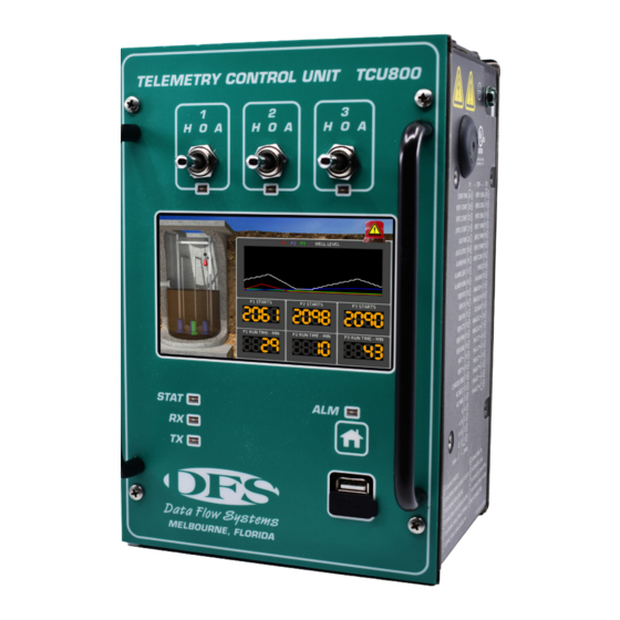
- Page 1 Data Flow Systems, Inc. T C U 8 0 0 Q u i c k S t a r t G u i d e...
- Page 2 NOTICE Data Flow Systems, Inc. assumes no responsibility for any errors that may appear in this document, nor does it make any commitment to update the information contained herein. However, questions regarding the information contained in this document are welcomed.
- Page 3 TCU800 and NOT its predecessor the TCU001. Detailed information on wiring the I/O, and configuring and using the TCU800 can be found in the TCU800 Installation and Operation Manual (see DFS website for the PDF version of this manual).
-
Page 4: Parts List
(DFS equipment, or RS-485 or RS-232 Modbus compatible devices). When used as a programmable device, the TCU800 can control up to 6 digital output devices, and monitor up to 18 digital and 4 analog input devices. It also features an expansion card slot on the top side which can be used to add additional I/O for specialized applications. - Page 5 Pollution Degree 2 • Safety Approval: UL listed for Process Control Equipment (UL1092) Features • Backward compatibility with Data Flow Systems’ TAC Pack TCU001 • Integrated 10/100 network adapter to allow remote access via SSH client over a local area network •...
- Page 6 • RS-485 Modbus fieldbus half-duplex serial interface enables communication with industry standard devices and VFD motor controllers • Configurable, auxiliary digital input can be used with pulse-type flow meters and rain gauges • Standard RS-232 Modbus radio interface acts as an interface to external industry standard radios •...
- Page 7 P1-8 BAT+ Backup battery positive terminal <24V / Not Rated P1-9 BAT- Backup battery negative terminal <24V / Not Rated P1-10 BEMGND Isolated ground (wire to BEM001, pin 12) <24V / Not Rated P1-11 BEM_PWR Isolated power (wire to BEM001, pin 10) <24V / Not Rated P1-12 BEM_CTS...
- Page 8 P3-13 SHIELD Internally connected to EARTH; cable shield for Ground analog monitor signals P3-14 IN_COM_3 Common return for thermal and seal failure digital 10-30VAC/DC, inputs 100mA RTN P3-15 MTR3_THERM Motor 3 temperature monitor input 10-30VAC/DC, 10mA P3-16 MTR2_THERM Motor 2 temperature monitor input 10-30VAC/DC, 10mA P3-17...
-
Page 9: Safety Precautions
P2-17 TXD_232 RS-232 transmit data to external device <24V / Not Rated P2-18 RXD_232 RS-232 receive data from external device <24V / Not Rated P2-19 RS-232 ground <24V / Not Rated P2-20 SHIELD Internally connected to EARTH; cable shield for analog Ground monitor signals P2-21... - Page 10 • Ensure that the unit is connected to earth ground during normal use. • Precautionary measures must be observed when installing, operating, and servicing the TCU in order to prevent shock from voltages present. • If the TCU is to be installed into an existing control panel, make sure that all breakers are shut off before starting the installation.
-
Page 11: Installation
The LCD is best viewed at slightly below eye level. Pre-Installation Modification Use snips, pliers, or a razor to remove the retention clips from P-connectors. Once the retention clip is removed, the P-connector will be able to be used with the TCU800. - Page 12 Applying power to the TCU800 will turn it on. To safely turn off the TCU800, hold down the Home button for 5 seconds. To turn the TCU800 on after a safe shutdown, press the Home button once. To force a reset of the TCU800, hold the Home button for 11 seconds.
- Page 13 The graphic to the right depicts how each of the TCU's three optional connector types can be attached to the unit. The first option uses the Spring-Clamp Connector Tool, which can be ordered from DFS. See the TCU800 Installation and Operation Manual for information on ordering connectors and the connector tool.
- Page 14 Wiring AC Power The maximum wire size to TCU connectors is 12 AWG. Use stranded copper conductors only with a minimum rating of 75°C. The recommended circuit breaker is 10 Amp maximum. When using connectors with screw-type terminals, tighten screw terminals to a maximum 7 in-lb (.79 Nm).
- Page 15 Press and hold the TCU’s home button to turn the unit on or enter a “soft off” state. The LCD screen indicates the state (on or off) of the TCU800. When turning the unit on, there will be a delay while the LCD screen is activated: the unit is considered ON when all of the front-panel LEDs are illuminated for a power- on lamp test.
- Page 16 Navigate through the TCU800 interface by swiping across the touchscreen either left or right. After swiping, the screen will turn black and display the new screen in a moment. In order to configure the TCU800, tap on the text and numbers in order to adjust their values. When you tap on a button in the interface it will highlight that button.
-
Page 17: Telemetry Configuration
Setup Configuring the TCU800 is done from the Settings screen. First ensure the H-O-A switches are all in the HAND or OFF position. Then navigate to the Settings screen by tapping the screen, opening the left Navigation Menu by tapping , scroll down using an upward swipe, and tap to select Settings. - Page 18 Moving the H-O-A switches to Auto at any point while in the Settings or Advanced Settings screen will terminate the session and return to the last viewed screen without saving any changes. Configuration Settings Grouped configurations are found on the Settings screen. The following is a table with the locations of each configuration.
- Page 19 Auto-Configuring At this time, using a TCU001 PLC configuration will cause an error in the TCU800. To avoid this, first transfer the existing configuration of the TCU800 using HT4 PLC editor. Then save the .plc file, create an auto-config file, and upload it to the appropriate station you want to auto-config.
- Page 20 Device Manager is connected and has not been formatted as a Configuration USB, it will ignore it. For detailed instructions for integrating the TCU with your telemetry system, see the TCU800 Installation and Operation Manual. Touchscreen-invoked Functions Detailed information on these functions can be found in the TCU800 Installation and Operation Manual.
-
Page 21: Maintenance
(next section) for instructions on obtaining replacement parts. Return Authorization (RA) Procedure In the event that a unit fails, during or after the warranty period, it may be returned to Data Flow Systems to be repaired or replaced. All RA's will be subject to standard shipping and handling charges. Minimum handling charges will be assessed in most cases for work such as Radio Tuning, Backplanes, "No Problem Found,"... -
Page 22: Warranty
Refer to your Warranty Certificate, or the Warranty Statement included with your contract, for details on the terms of your warranty. If you lose your Warranty Certificate/Statement, contact Data Flow Systems’ Sales Department to obtain the warranty terms and to replace your Warranty Certificate/Statement. - Page 23 Notes:...
- Page 24 Notes:...
- Page 25 Data Flow Systems, Inc. 605 N. John Rodes Blvd. Melbourne, FL 32934 321-259-5009 www.dataflowsys.com...
Need help?
Do you have a question about the TCU800 and is the answer not in the manual?
Questions and answers