
Related Manuals for FMS 1100MM PC-21


Summary of Contents for FMS 1100MM PC-21
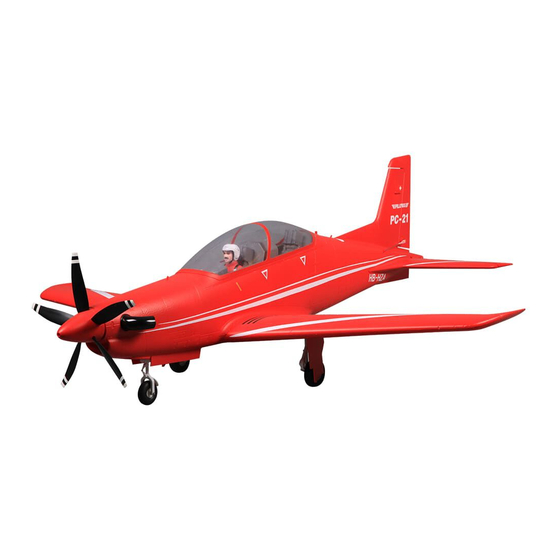
- Page 1 1100MM PC-21 FMSMODEL.COM REALISTIC RIGID STABLE RETRACT & FLAPS INSTALLED STRONG DURABLE EPO SMOOTH FLYING PERFORMANCE...
-
Page 4: Table Of Contents
High quality anti-collision foam box FMS invest not only on the airplane design but also on the foam box. CNC molding for the box provides a snug fit for the airplane parts. Extensive work on the 3D graph makes the final work detailed and strong. Before production, crash tests against the four angles and six sides are conducted. -
Page 5: Contents Of Kit
Wingspan: 1100mm (43.3in) Overall Length: 1235mm (48.6in) Flying Weight: Around 1680g (59.3oz) Motor Size: Brushless 3541-KV750 Wing Load: 71.8 g/dm² (0.16oz/in²) Wing Area: 23.4 dm² (362.7 sq.in) ESC: 40A Servo: 9g Servo x 7 Contents of Kit Before assembly, please inspect the contents of the kit. The photo below details the contents of the kit and labels. -
Page 6: Assemble The Plane
Horizontal Tail Installation 1. Slide the horizontal tail into the slot in the rear of the fuselage. Ensure the control horn is face . fig1 PA2.6*10 fig2... - Page 7 fig3...
- Page 8 4. Install the wing a. Remove the canopy hatch b. Guide the Multi Connector wires through the hole located in the bottom of the fuselage as shown. c. Align the wing with the fuselage and secure into position using screws HKM3.0*25mm as shown. fig4 HKM3.0*25 fig5...
- Page 9 5. Glue the airspeed head and insert it into the wing as shown in Figure 6. fig6...
-
Page 10: Battery And Radio Installation
Battery and radio installation fig8 fig7 fig9... -
Page 11: Get Your Model Ready To Fly
Get your model ready to fly Important ESC and model information The ESC included with the model has a safe start. If the motor battery is connected to the ESC and the throttle stick is not in the low throttle or off position, the motor will not start until the throttle stick is moved to the low throttle or off position. -
Page 12: Check The Control Throws
Check the control throws The suggested control throw setting for FMS MODEL are as follows (dual rate setting): Tips: At first flight, fly the model in low rate. The first time you use high rates, be sure to fly at low to medium speeds. -
Page 13: Clevis Installation
Clevis Installation a. Pull the tube from the clevis to the linkage. b. Carefully spread the clevis, then insert the clevis pin into the desired hole in the control horn. c. Move the tube to hold the clevis on the control horn. Control Horn and Servo Arm Settings The table shows the factory settings for the control horns and servo arms. -
Page 14: Install The Propeller And Spinner
Install the propeller and spinner Assemble the spinner and propeller as shown below. Check the C.G. (Center of Gravity) When balancing your model, adjust the motor battery as necessary so the model is level or slightly nose down. This is the correct balance point for your model. After the first flights, the CG position can be adjusted for your personal preference. -
Page 15: Before Flying The Model
Before flying the model Find a suitable flying site Find a flying site clear of buildings, trees, power lines and other obstructions. Until you know how much area will be required and have mastered flying your plane in confined spaces, choose a site which is at least the size of two to three football fields - a flying field specifically for R/C planes is best. -
Page 16: Flying Course
Flying course Take off While applying power, slowly steer to keep the model straight. The model should accelerate quickly. As the model gains flight speed you will want to climb at a steady and even rate. PC-21 will climb out at a nice angle of attack (AOA). -
Page 17: Troubleshooting
Troubleshooting... -
Page 18: Spare Parts List Content
Spare parts list content Fuselage FMSPP101 FMSPP102 Main Wing Set FMSPP103 Horizontal Stabilizer FMSPP104 Cockpit FMSPP105 Spinner FMSPP106 Air Speed Head FMSPP107 Exhaust pipe FMSPP108 Landing Gear Set FMSPP109 Main Landing Gear System FMSPP110 Front Landing Gear System FMSPP111 Linkage Rod FMSPP112 Screws FMSPP113... -
Page 19: Esc Instruction
ESC instruction...
Need help?
Do you have a question about the 1100MM PC-21 and is the answer not in the manual?
Questions and answers