
Related Manuals for Safety Engineering Self Belay


Summary of Contents for Safety Engineering Self Belay
- Page 1 OPERATIONS MANUAL Last revision: 2020-12-14 WARNING: INSTALLERS AND OPERATORS MUST READ THIS OPERATIONS MANUAL AND COMPLETELY UNDERSTAND ALL REQUIREMENTS AND AGERE TO MAINTENANCE GUIDELINES.
-
Page 2: Table Of Contents
8. Device specification ............................6 9. Installation ............................... 7 9.1. Prepare the Self Belay device ......................7 9.2. Installation on steel cable ........................8 9.3. Installation on textile webbing ......................9 9.4. Installation of quicklinks to user harness .................. 10 9.5. -
Page 3: Introduction And Overview
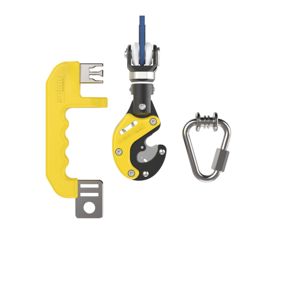
1. Introduction and overview The Self Belay is a safety connector that is used for securing oneself to the end of an auto belay device. It adds to the safety of climbing through its unique design. The Self Belay Set is comprised of three main parts that come packaged inside the box. -
Page 4: Product Identification
Signature / Подпис Signature / Подпис The property and use of this design are protected by the law for the exclusive use of Safety Engineering Ltd. Собствеността на този дизайн е защитена от Закона за авторски права на Сейфти Инженеринг ООД... -
Page 5: Conformity Assessment
Perfect Descent Direct Drive and Perfect Descent Speed Drive manufactured by C3 Manufacturing LLC (Perfect Descent)*(see notice below) NOTICE: The Self Belay body can be retrofitted to C3 Manufacturing LLC (Perfect Descent) devices, but Safety Engineering has no formal contract with the manufacturer. Therefore, the... -
Page 6: Device Specification
8. Device specifications Dimensions as installed: Width: 63 mm Height: 200 mm (including quick link Delta assembly) Depth: 27 mm Weight as installed: 320 g Main body Quicklink delta assembly Material: EN AW 2017A, AISI 304 Material: AISI 304 Min. breaking strength: 20 kN axial load Min. -
Page 7: Installation
A flat screwdriver • Set of pliers For installation on steel cable, see sections Prepare the Self Belay device and Installation on steel cable. For installation on textile webbing, see sections Prepare the Self Belay device and Installation on textile webbing. - Page 8 Remove the lock washer with a flat screwdriver from the folding bolt: Lift and remove the pin assembly and the plastic washers: 111v Tsarigradsko Shose blvd, 1784 Sofia, Bulgaria | info@safetyeng.eu | www.safetyeng.eu page 8...
-
Page 9: Installation On Steel Cable
9.2. Installation on steel cable With the Self Belay device prepared, position the cable between the plastic washers: Insert the folding bolt and lock it to the body of the swivel. Make sure the bolt is securely fastened and cannot be detached from the device by hand. -
Page 10: Installation On Textile Webbing
9.3. Installation on textile webbing Self Belay can be installed on textile webbing of width 20 mm. Installation on other webbing sizes is not recommended. Before you proceed, remove the plastic washers and keep them together with the original device packaging. -
Page 11: Installation Of Quicklinks To User Harness
Refer to section Compatibility with autobelay devices and harness for a list of compatible harnesses. WARNING: Use only harnesses compatible with the Self Belay. Usage of other types of harnesses is not supported and does not guarantee end user safety! -
Page 12: Installation Of Self Belay Key
9.5. Installation of Self Belay key The Self Belay key is intended to be attached securely at a safe location where the user connects and disconnects themselves from the device. The key features rectangular openings for attachment by means of webbing, and a circular hole for a connector or other attachment... - Page 13 To detach: • Take the Self Belay key and insert it all the way in the opening on the side of the Self Belay. • Pull the quicklink away from the device. • You are now disconnected from the Self Belay 111v Tsarigradsko Shose blvd, 1784 Sofia, Bulgaria | info@safetyeng.eu | www.safetyeng.eu...
-
Page 14: Inspection And Maintenance
11.1. Daily inspection Self Belay device and its components shall be inspected daily before the start of each work day in order to ensure their safety and smooth operation. The following procedures shall be followed in order to ensure optimal safety and efficiency. - Page 15 3.Self Belay key measurement Measure the width of the middle pin of the Self Belay key as shown; measured value should be above 2.8 mm. This dimension is between 3.6 and 3.8 mm as manufactured; if the measured value is close (but still above) 2.8 mm, consider ordering replacement keys.
- Page 16 If the swivel is deformed, damaged or shows signs of cracking, stop using the device immediately. Contact Safety Engineering for a replacement. 5. Swivel pin check Inspect the swivel pin for damage or deformation; stop using the device immediately if the...
- Page 17 With the quicklink inserted all the way, remove the key from the device; key should slide out easily without excessive effort. When the key is out of the device, verify that the Self Belay is firmly locked and the quicklink cannot be taken out.
-
Page 18: General Care
• Cleaning (device only): Clean the exterior of the Self Belay device with a damp cloth with small amount of mild detergent. Do not submerge the device in water! Let the device dry completely before next use. -
Page 19: Daily Checklist
If problem persists, contact manufac- jams? turer for replacement device. Missing or deformed Stop using the key immediately. Daily middle pin? Self Belay key Middle pin thickness Stop using the key immediately. Daily below 2.8 mm? Badly damaged or Stop using the quicklink immediately. -
Page 20: Annual Maintenance And Recertification
The new or refurbished devices are warranted for a further 12 months from the date of arrival to the client. Any damages that make the Self Belay unsafe within the warranty period will be dealt with as defined in section Warranty information Warranty information. - Page 21 Component Image OEM number Quantity Locking disc, central SE.SB.P00005 Locking disc, side SE.SB.P00006 Locking anchor, left SE.SB.P00007L Locking anchor, right SE.SB.P00007R Sheet spring SE.SB.P00008 Positioning spring SE.SB.P00009 Positioning roller SE.SB.P00010 Side cover, right SE.SB.P00011 Side cover, left SE.SB.P00012 111v Tsarigradsko Shose blvd, 1784 Sofia, Bulgaria | info@safetyeng.eu | www.safetyeng.eu page 21...
- Page 22 Component Image OEM number Quantity Bushing SE.SB.P00015 Folding spring bolt SE.SB.P00018 Swivel pin SE.SB.P00019 Torsion spring - left SE.SB.P00032L Torsion spring - right SE.SB.P00032R Lock washer, E-type DIN 6799 - 7 Flat round head rivet DIN 660 3x28 Hex socket head cap ISO 4762 M4x22 A2-70 screw Hex nut...
-
Page 23: Lifespan
ISO 8734 4x10 12. Lifespan The self belay has a lifespan of 12 months, which can be extended up to 5 years with re- certification. It is imperative that the clients send their self belays for inspection every year as described in section Annual Maintenance of this manual, in order to ensure safe operation and extended lifespan of the devices. - Page 24 14. Further information If you have further questions or inquiries, please contact us by email (support@safetyeng.eu) or through our website (https://safetyeng.eu). 111v Tsarigradsko Shose blvd, 1784 Sofia, Bulgaria | info@safetyeng.eu | www.safetyeng.eu page 24...
Need help?
Do you have a question about the Self Belay and is the answer not in the manual?
Questions and answers