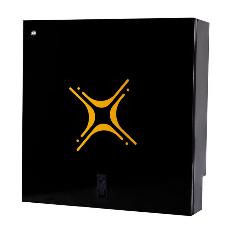
Summary of Contents for Solar MD SS4074-01
- Page 1 Solar MD (PTY) ltd. Unit 23, Alternator Park Montague Gardens 7441 Cape Town, South Africa INSTALLATION MANUAL SS4074-01 Advanced Lithium-Ion battery 24V / 48V...
-
Page 2: Table Of Contents
Solar MD (PTY) ltd. Montague Gardens 7441 E: info@solarmd.co.za T: (021) 555 2181 . Cape Town, South Africa SS4074-01 INSTALLATION MANUAL v1.4 Introduction Product Description Product Specifications Errors or Inaccuracies Copyrights Safety Information ⚠ Warnings ⚠ Cautions... -
Page 3: Introduction
Solar MD Lithium Ion phosphate (LiFePO4) energy storage solutions. Product Description The SS4074-01 battery solution is available in one standard size and can be paralleled to meet most residential applications. The rated voltage is 51.2V nominal (to suit 48V systems) or 25.6V nominal (to suit 24V systems). -
Page 4: Product Specifications
Copyrights All information in this document is subject to the copyright of Solar MD (Pty) Ltd. Additional information is available upon request. Safety Information This manual contains important instructions and warnings that must be followed when using SS4074-01. -
Page 5: Specification
Unit 23, Alternator Park Solar MD (PTY) ltd. Montague Gardens 7441 E: info@solarmd.co.za T: (021) 555 2181 . Cape Town, South Africa SS4074-01 INSTALLATION MANUAL v1.4 Specification Lithium Iron Battery Chemistry Scalability Yes Phosphate (LiFePO4) Battery Module SS4074-01 ... -
Page 6: Mechanical Installation Batteries
T: (021) 555 2181 . Cape Town, South Africa SS4074-01 INSTALLATION MANUAL v1.4 Mechanical installation Figure 1: Rear Battery Bracket Use the correct mounting screws for the correct wall surface. Screw heads should not be larger than 16mm in diameter. The Battery is only to be installed in the upright position with a maximum tilt angle of 30 degrees. -
Page 7: Installing Bottom Cover Plate
. Cape Town, South Africa SS4074-01 INSTALLATION MANUAL v1.4 Installing bottom cover plate Figure 3: Bottom cover installation for single or dual cable exit points The Battery comes with two covers for single or dual cable exit points. Use the 1 or 2... -
Page 8: Electrical Installation
T: (021) 555 2181 . Cape Town, South Africa SS4074-01 INSTALLATION MANUAL v1.4 Electrical installation Step 1 . Before connecting anything be sure that the battery ON/OFF switch is in the OFF position. (fig 4 pos 3) Figure 4: BMS board component locations... - Page 9 . Cape Town, South Africa SS4074-01 INSTALLATION MANUAL v1.4 Connecting Inverters/chargers/UPS to the battery unit while it is ON can cause big sparks due to capacitors inside the connected device. This could cause serious injuries. Use the appropriately sized cable for connected devices, calculated based on the rated current of the battery and inverter as well as cable length and environmental conditions.
- Page 10 T: (021) 555 2181 . Cape Town, South Africa SS4074-01 INSTALLATION MANUAL v1.4 CANBUS connection. Bms EM used C AN 2.0B @ 500 kbps. Connecting other devices operating at a different speed rate is not allowed. For connection, please use ...
- Page 11 . Cape Town, South Africa SS4074-01 INSTALLATION MANUAL v1.4 Commissioning Step 1 . Ensure all DC cables are tightened according to specifications. Step 2 . If the battery operates in parallel with other Energy sources, make sure that the difference between battery voltage and DC bus is not more than 2.5V.
-
Page 12: Multicolor Multipurpose Button
Figure 7 : Multicolor / Multipurpose button Button functions The new Solar MD Multipurpose button has an extended functionality in combination with the BMS-EM v10.01. The Multipurpose Button can be used to directly execute 6 predefined functions and a shutdown instruction. In combination with the 6 Indication LEDs on BMS-EM v10.01, the user can choose between each function by holding the button until the LED count... -
Page 13: Button Indication
SoC for 5 intervals. The flashing code for discharge represents the opposite from charge - study color for 1 interval and slow loss of color following illumination interruption. Solar MD users refer to both as charging / discharging waves. -
Page 14: Bms Warnings And Errors
T: (021) 555 2181 . Cape Town, South Africa SS4074-01 INSTALLATION MANUAL v1.4 BMS Warnings and Errors Method of displaying general warnings and errors: Figure 8 : Display general warnings and errors, Main stat LEDs and Indication LEDs. - Page 15 E: info@solarmd.co.za T: (021) 555 2181 . Cape Town, South Africa SS4074-01 INSTALLATION MANUAL v1.4 Warning codes. Figure 9. Indication LEDs: (1,2,3) orange left and (4,5,6) green right. In combination with Orange Stat LED (WARNING) ◼ + ...
- Page 16 E: info@solarmd.co.za T: (021) 555 2181 . Cape Town, South Africa SS4074-01 INSTALLATION MANUAL v1.4 Error codes. Figure 10. Indication LEDs: (1,2,3) orange left and (4,5,6) green right. In combination with Red Stat LED (ERROR) ◼ + ...
- Page 17 E: info@solarmd.co.za T: (021) 555 2181 . Cape Town, South Africa SS4074-01 INSTALLATION MANUAL v1.4 Error codes continued. Figure 11 Indication LEDs: (1,2,3) orange left and (4,5,6) green right. In combination with Red Stat LED (ERROR) ◼ ...
-
Page 18: Canbus Warnings
T: (021) 555 2181 . Cape Town, South Africa SS4074-01 INSTALLATION MANUAL v1.4 CANBUS Warnings. Figure 12 CANBUS Termination resistor and Warning LED location The Orange LED (WARN) is used to display warnings for canbus only. Reading this warning is possible with pulse counting. -
Page 19: Troubleshooting
The BMS is set for different number cells in series as the actually Contact your installer or Solar MD support team installed Battery cell voltage way too low. Fill in the failure report and send to info@solarmd.co.za... - Page 20 @0.3C discharge / charge current. If so adjust the values above. Please check if your inverter charger has been approved by Solar MD and it is CAN compatible. For the latest Solar MD installation documents go to: solarmd.co.za...


Need help?
Do you have a question about the SS4074-01 and is the answer not in the manual?
Questions and answers