Emerson 781S Quick Start Manual
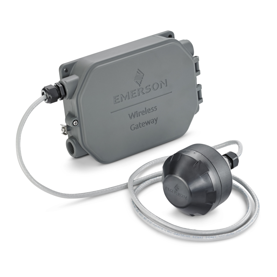
Wireless smart antenna
Hide thumbs
Also See for 781S:
- Quick start manual (28 pages) ,
- Reference manual (134 pages) ,
- Reference manual (78 pages)

Related Manuals for Emerson 781S


Summary of Contents for Emerson 781S
- Page 1 Quick Start Guide 00825-0700-4410, Rev AB October 2020 Emerson Wireless 781S Smart Antenna...
- Page 2 October 2020 Safety messages NOTICE This guide provides basic guidelines for the Emerson Wireless 781S Smart Antenna. It does not provide instructions for diagnostics, maintenance, service, or troubleshooting. Refer to the Emerson Wireless 1410S Gateway and 781S Smart Antenna Reference Manual for more information and instructions.
- Page 3 October 2020 Quick Start Guide Verify operation......................... 11 Product certifications......................... 12 Reference data........................... 23 Quick Start Guide...
- Page 4 Quick Start Guide October 2020 Emerson.com...
-
Page 5: Wireless Planning
Quick Start Guide Wireless planning Power up sequence The Emerson Wireless Smart Antenna and wireless I/O should be installed and functioning properly before the power modules are installed in any wireless field devices. Wireless field devices should also be powered up in order of proximity from the antenna beginning with the closest. - Page 6 Quick Start Guide October 2020 Antenna position The Emerson 781S Smart Antennas should be positioned vertically and approximately 3 ft. (1 m) from large structures, buildings, or conductive surfaces to allow for clear communication to other devices. If installing multiple antennas, it is important that the antennas have three feet of horizontal separation from one another.
-
Page 7: Intended Use
October 2020 Quick Start Guide Intended use System architecture The smart antenna must be used in conjunction with a network manager or network gateway. The smart antenna then functions as a translator between the wired network and a wireless field network. Figure 2-1: Example System Architecture Quick Start Guide... -
Page 8: Physical Installation
4. Use a 5/16-in. wrench to tighten the screw into the housing. Figure 3-1: Mounting Power and data wiring The Emerson 781S is completely prewired and only needs to be connected and powered on the Gateway end. The housing is permanently sealed on the Emerson 781S. In the Gateway:... - Page 9 Quick Start Guide Figure 3-2: Wiring Guide A. Power B. Data Red - positive Blk - negative Wht - RS-485 comm A Blu - RS-485 comm B Figure 3-3: Emerson Wireless 781S A. Power output B. RS-485 comm Quick Start Guide...
-
Page 10: Best Practices
Twisted shielded pair cable is generally used to wire the serial connection to the Gateway. The Smart Antenna should be installed in a central location of the wireless field network so that it has the most direct connections to wireless devices as possible. Emerson.com... - Page 11 Gateway, its operation must be verified through the Gateway end of the connection. Power up sequence The second and third LED’s in the Emerson 1410S correlate to the first and second terminal connections. These lights should be green when the antenna is connected properly.
- Page 12 RF spectrum. Nearly every country requires this type of product certification. Emerson is working with governmental agencies around the world to supply fully compliant products and remove the risk of violating country directives or laws governing wireless device usage.
- Page 13 October 2020 Quick Start Guide Les changements ou les modifications apportés à l'équipement qui n'est pas expressément approuvé par Rosemount, Inc. pourraient annuler l'autorité de l'utilisateur à utiliser cet équipement. Ordinary location certification As standard, the device has been examined and tested to determine that the design meets the basic electrical, mechanical, and fire protection requirements by a nationally recognized test laboratory (NRTL) as accredited by the Federal Occupational Safety and Health Administration (OSHA).
- Page 14 3. The measured capacitance between the equipment enclosure and metallic conduit adapter is 21pF. This must be considered only when the Model 781S is integrated into a system where the process connection is not grounded. ATEX Intrinsic Safety...
- Page 15 3. The measured capacitance between the equipment enclosure and metallic conduit adapter is 21pF. This must be considered only when the Model 781S is integrated into a system where the process connection is not grounded. International I7 IECEx Intrinsic Safety Certificate IECEx BAS.20.0021X...
- Page 16 Quick Start Guide October 2020 6.10 Declaration of Conformity Emerson Wireless 781SA Smart Antenna Emerson.com...
- Page 17 October 2020 Quick Start Guide Quick Start Guide...
- Page 18 Quick Start Guide October 2020 Emerson.com...
- Page 19 October 2020 Quick Start Guide 6.11 Declaration of Conformity Emerson Wireless 781SC Smart Antenna Quick Start Guide...
- Page 20 Quick Start Guide October 2020 Emerson.com...
- Page 21 October 2020 Quick Start Guide Quick Start Guide...
- Page 22 Quick Start Guide October 2020 6.12 China RoHS table Emerson.com...
- Page 23 October 2020 Quick Start Guide Reference data For information on product specs, dimensional drawings, ordering information or the complete reference manual, see Emerson.com. Figure 7-1: Hazardous Location Installation Option N: No intrinsically safe (IS) outputs, for installation in safe areas only...
- Page 24 The Emerson logo is a Twitter.com/Rosemount_News trademark and service mark of Emerson Electric Facebook.com/Rosemount Co. Rosemount is a mark of one of the Emerson Youtube.com/user/ family of companies. All other marks are the RosemountMeasurement property of their respective owners.
Need help?
Do you have a question about the 781S and is the answer not in the manual?
Questions and answers