Table of Contents
Advertisement
Available languages
Available languages
Quick Links
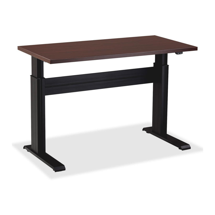
LLR81954
LLR81955
VERSION DATED: 11/25/13
READ ALL THE INSTRUCTIONS BEFORE BEGINNING.
DO NOT OPERATE THE UNIT UNTIL IT IS FULLY ASSEMBLED.
ITEM #
PART #
1
VARIES
LT WORKSURFACE
2
801049
LT LEG ASSEMBLY LEFT
3
801064
LT MOTOR & BRACKET ASSEMBLY
4
53013
SPLIT LOCK WASHER ¼
5
53055
SOCKET HEAD CAP SCREW 1/4-20 x 7/16
6
VARIES
LT HEX ROD ASSEMBLY
7
801050
LT LEG ASSEMBLY RIGHT
8
VARIES
SERIES 4 CROSS SUPPORT
9
53024
5/16-18 x 1/2 BUTTON HEAD SOCKET SCREW
10
53025
5/16 LOCK WASHER
11
800934 V1 CROSS SUPPORT END CAP
12
VARIES
LT U-CHANNEL
13
52990
LT CONTROL BOX
14
51708
M5 x 18MM SQ/PH/WSHR HEAD WOOD SCREW
15
52900
6 x 3/4 PHILLIPS PAN HEAD SHEET METAL SCREW
16
51951
WIRE MANAGEMENT J
17
SCREW
10 x 5/8 PHILLIPS TRUSS HEAD SCREW
18
52989
HAND SWITCH
19
52604
3/16" CABLE CLAMP
INSTRUCTION # 53026
TOOLS REQUIRED FOR ASSEMBLY:
#2 PHILLIPS HEAD DRIVER BIT
#2 SQUARE HEAD DRIVER BIT
7/32" HEX HEAD DRIVER BIT OR
ALLEN WRENCH
TAPE MEASURE
DESCRIPTION
Hardware Pack #53059
ELECTRIC HEIGHT ADJUSTABLE WORKSTATION ASSEMBLY
INSTRUCTIONS:
STEP 1: Lay the worksurface 1 on a protected surface with the pilot holes
facing up. (There are pilot holes for attaching most of the workstation's
components.) Place the left leg assembly 2 on the worksurface
aligning the holes in the worksurface support with the pilot holes in the
worksurface.
STEP 2: Insert the longer hex rod on the hex rod assembly 6 through the
hex drive on the motor assembly 3 and into the hex drive near the top of
the leg assembly 2. You may need to turn the hex rod assembly slightly to
align it with the hex drive.
STEP 3: Insert (2) washers 4 onto (2) socket screws 5. Thread these
through the motor bracket and into the worksurface support. See Detail A.
Fully tighten.
QTY.
5
1
1
4
1
2
2
1
1
1
4
4
3
2
MOTOR
1
BRACKET
1
32
2
1
1
1
1
DETAIL A
LONG
END
WORKSURFACE
SUPPORT
6
STEPS 1-3
2
A
1
PAGE 1 OF 4
Advertisement
Table of Contents

Related Manuals for Lorell LLR81954


Summary of Contents for Lorell LLR81954
- Page 1 #2 PHILLIPS HEAD DRIVER BIT #2 SQUARE HEAD DRIVER BIT STEP 1: Lay the worksurface 1 on a protected surface with the pilot holes LLR81954 7/32" HEX HEAD DRIVER BIT OR facing up. (There are pilot holes for attaching most of the workstation's ALLEN WRENCH components.) Place the left leg assembly 2 on the worksurface...
- Page 2 STEP 4: Place the right leg assembly 7 on the worksurface 1. Insert the end of the hex rod 6 into the hex drive on the right leg assembly. You may need to turn the hex rod slightly to align the hex rod with the hex drive in the leg assembly.
-
Page 3: Troubleshooting
Level the workstation if required by turning the leveling glides clockwise TROUBLESHOOTING: (from the top) on the low corners of the unit. If you are having a problem with the table operation, E-mail Lorell@sprich.com or fax 404-472-9063. Please provide the following information: 1. - Page 4 INSTRUCTIONS TO INSTALL A TRACK ON THE ELECTRIC HEIGHT ADJUSTABLE WORKSTATION: STEP 1: Place the front of the track 3 against the bottom of the worksurface 2 and the back of the track against the U-channel 1. STEP 2: Align the holes in the track 3 with one of the sets of pilot holes in the U-channel 1 keeping the front of the track 1/8" to 5/8" from the front of the worksurface 2.
-
Page 5: Outils Requis Pour L'assemblage
ÉTAPE 1 : Posez le poste de travail 1 sur une surface protégée, avec les PERCEUSE N°2 avant-trous orientés vers le haut. (Des avant-trous ont été percés pour fixer LLR81954 MÈCHE À TÊTE CARRÉE DE PERCEUSE N°2 la plupart des composants du poste de travail.) Placez l'assemblage de pied MÈCHE À... -
Page 6: Poste De Travail
ÉTAPE 4 : Placez l'assemblage de pied droit 7 sur le poste de travail 1. Insérez l'extrémité de la tige hexagonale 6 dans la transmission hexagonale sur l'assemblage de pied droit. Vous devrez peut-être tourner la tige hexagonale légèrement pour aligner la tige hexagonale avec la transmission hexagonale dans l'assemblage de pied. -
Page 7: Procédure De Mise En Service
(en partant du sommet) sur les coins inférieurs du poste. Si vous rencontrez des problèmes pour utiliser cette table, écrivez un courriel à l'adresse Lorell@sprich.com ou envoyez une télécopie au 404-472-9063. Veuillez inclure les informations suivantes : 1. Nom complet 2. - Page 8 INSTRUCTIONS POUR INSTALLER UN RAIL SUR LE POSTE DE TRAVAIL À HAUTEUR RÉGLABLE ÉLECTRIQUE: ÉTAPE 1 : Placez l'avant du rail 3 contre le bas du poste de travail 2 et l'arrière du rail contre la gaine en U 1. ÉTAPE 2 : Alignez les trous du rail 3 avec l'un des jeux d'avant trous de la gaine en U 1, en gardant l'avant du rail de 1/8 à...
- Page 9 AJUSTE ELÉCTRICO DE ALTURA BROCA DE CRUZ #2 PASO 1: Coloque la superficie de trabajo 1 sobre una superficie protegida LLR81954 BROCA CUADRADA #2 con los orificios guía viendo hacia arriba. (La mayoría de los componentes de la estación de trabajo tienen orificios guía para la unión). Coloque el ensamble...
- Page 10 PASO 4: Coloque el ensamble de la pata derecha 7 sobre la superficie de trabajo 1. Inserte el extremo de la varilla hexagonal 6 en el orificio hexagonal del ensamble de la pata derecha. Es posible que deba girar un poco la varilla hexagonal para alinearla con el orificio hexagonal en el ensamble de la pata.
-
Page 11: Procedimiento De Arranque
SOLUCIÓN DE PROBLEMAS: las esquinas inferiores de la unidad. Si tiene algún problema con el funcionamiento de la mesa, envíe un mensaje de correo electrónico a lorell@sprich.com o un fax al 404-472-9063. Recuerde proporcionar la siguiente información: 1. Nombre completo 2. - Page 12 INSTRUCCIONES PARA INSTALAR UN RIEL EN LA ESTACIÓN DE TRABAJO CON AJUSTE ELÉCTRICO DE ALTURA: PASO 1: Coloque el frente del riel 3 sobre la parte inferior de la superficie de trabajo 2 y la parte trasera del riel sobre el canal 1. PASO 2: Alinee los orificios en el riel 3 con uno de los juegos de orificios guía en el canal 1 manteniendo el frente del riel de 1/8”...
Need help?
Do you have a question about the LLR81954 and is the answer not in the manual?
Questions and answers