Table of Contents
Advertisement
Available languages
Available languages
Quick Links
SR 80
SR 80
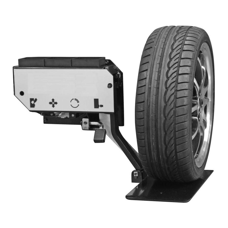
DISPOSITIVO DI SOLLEVAMENTO RUOTA
WHEEL LIFTING DEVICE
DISPOSITIF ÉLEVATEUR DE ROUES
RADHEBEVORRICHTUNG
DISPOSITIVO ELEVADOR DE RUEDAS
MANUALE ISTRUZIONI ............................
INSTRUCTION MANUAL ............................
MANUEL D'INSTRUCTIONS ....................... 15
BETRIEBSANLEITUNG .............................. 21
MANUAL DE INSTRUCCIONES ................... 27
3
9
Advertisement
Chapters
Table of Contents

Related Manuals for SICE SR 80

Summary of Contents for SICE SR 80
- Page 1 SR 80 SR 80 DISPOSITIVO DI SOLLEVAMENTO RUOTA WHEEL LIFTING DEVICE DISPOSITIF ÉLEVATEUR DE ROUES RADHEBEVORRICHTUNG DISPOSITIVO ELEVADOR DE RUEDAS MANUALE ISTRUZIONI ......INSTRUCTION MANUAL ......MANUEL D'INSTRUCTIONS ....... 15 BETRIEBSANLEITUNG ......21 MANUAL DE INSTRUCCIONES ....27...
- Page 2 ITALIANO • Manuale d’uso...
-
Page 3: Table Of Contents
ITALIANO • Manuale d’uso SOMMARIO 1 - GENERALITA' ....................... 2 - CARATTERISTICHE TECNICHE ................... 3 - NORME GENERALI DI SICUREZZA ..................4 - DISPOSITIVI DI SICUREZZA .................... 5 - DISIMBALLO ........................ 6 - INSTALLAZIONE ........................................6.1 FISSAGGIO SOLLEVATORE ..................... 6.2 MONTAGGIO PEDANA ................... -
Page 4: Generalita
Questo manuale contiene solamente le ulteriori istruzioni necessarie per un corretto utilizzo del dispositivo di sollevamento ruota SR 80. 1 - GENERALITA’ Il dispositivo di sollevamento ruota SR 80, è stato creato quale accessorio a richiesta degli smontagomme SICE per agevolare il po- sizionamento della ruota da terra sull’autocentrante e viceversa. -
Page 5: Dispositivi Di Sicurezza
5 - DISIMBALLO Il dispositivo SR 80 viene fornito in cassa di legno di dimensione: mm. 550x550x250. Il peso del dispositivo imballato è di 36 kg. Dopo aver tolto l'imballaggio assicurarsi dell'integrità dell'apparecchio, controllando che non vi siano parti visibilmente danneggiate. -
Page 6: Fissaggio Sollevatore
ITALIANO • Manuale d’uso 6.1 FISSAGGIO SOLLEVATORE 1. Togliere la fiancata sinistra dello smontagomme 2. Smontare la protezione pedali dello smontagomme (vedi Fig. C). Sotto la protezione sono presenti 4 fori filettati per il fissaggio del sollevatore e un foro, di diametro maggiore dove inserire il tubo di alimentazione pneumatica. -
Page 7: Allacciamento Pneumatico
Il pedale comando deve essere azionato esclusivamente da parte di chi opera. 8 - USO Il dispositivo SR 80 é stato concepito per facilitare la movimentazione delle ruote da terra all’autocentrante e viceversa. Posizionamento ruota: 1. Sistemare la ruota in verticale sulla pedana. -
Page 8: Inconvenienti/Cause/Rimedi
1) Inserire correttamente il tubo dell’aria di alimentazione e verificare che fornisca la pressione necessaria. 2) Verificare che i tubi dell’SR 80 non siano ostruiti da piegature accidentali. ATTENZIONE: Se le indicazioni sopra elencate non riportano il dispositivo ad un corretto funzionamento o si riscontrino anomalie di diverso tipo, NON utilizzare il dispositivo e chiamare immediatamente il servizio tecnico di assistenza. - Page 9 ENGLISH • Instructions manual CONTENTS 1 - GENERAL INFORMATION ...................... 2 - TECHNICAL DATA ......................... 3 - GENERAL SAFETY REGULATIONS ..................4 - SAFETY DEVICES ......................5 - UNPACKING ......................... 6 - INSTALLATION ......................................... 6.1 FASTENING THE LIFTER ................... 6.2 INSTALLING THE PLATFORM ...................
-
Page 10: General Information
The instructions in this manual are therefore a supplement to the manual of the tyre changer, the information in which therefore continues to apply. This manual only contains the additional instructions required for correct use of the SR 80 wheel lifting de- vice. -
Page 11: Safety Devices
5 - UNPACKING The SR 80 is delivered in a 550x550x250 mm wooden box. The shipping weight is 36 kg. Once the machine has been unpacked, check to make use all its parts are present and that there are no visible signs of damage. -
Page 12: Fastening The Lifter
ENGLISH • Instructions manual 6.1 FASTENING THE LIFTER 1. Remove the left hand side panel of the tyre changer 2. Remove the tyre changer pedal guard (see Fig. C). Under the guard, there are 4 threaded holes for fastening the lifter and one larger diameter hole for the compressed air line. -
Page 13: Compressed Air Hook Up
2. Install the 8-6/8-6/6-4 T-union to restore the compressed air supply cut in the previous step, and have another compressed air connector ready to fit onto the union. 3. Connect the 6-4 diam. 800 mm long pipe leading from the SR 80 lifter to the union installed in the previous step (see Fig. N). -
Page 14: Troubleshooting
2) Check if the SR 80 air hoses are clogged or accidentally crimped. WARNING! If the suggestions detailed above do not bring the device back to good functional performance or if the problem is other than those listed above, DO NOT use the machine and contact your nearest SICE Technical Assistance Centre. - Page 15 FRANÇAIS • Manuel d’instructions SOMMAIRE 1 - GÉNÉRALITÉS ....................... 2 - CARACTÉRISTIQUES TECHNIQUES ................... 3 - NORMES DE SÉCURITÉ GÉNÉRALES ................... 4 - DISPOSITIFS DE SÉCURITÉ .................... 5 - DÉBALLAGE ........................ 6 - INSTALLATION ........................................... 6.1 FIXATION ELEVATEUR ................... 6.2 MONTAGE PLATE-FORME ...................
-
Page 16: Généralités
SR 80. 1 - GÉNÉRALITÉS Le dispositif élévateur de roues SR 80 a été créé comme accessoire en option des démonte-pneus SICE pour faciliter le positionnement de la roue depuis le sol sur le plateau autocentrant et inversement. -
Page 17: Dispositifs De Sécurité
6 - INSTALLATION ATTENTION! Les opérations d’installation du dispositif SR 80 doivent être réalisées exclusivement par du personnel qualifié. N.B.: Avant toute opération d’installation vérifier que le démonte-pneus est branché à chacune des sources d’alimentation. Vérifier en outre que le démonte-pneus est bien fixé au sol avec des chevilles à expansion pour éviter tout risque de bascule-... -
Page 18: Fixation Elevateur
FRANÇAIS • Manuel d’instructions 6.1 FIXATION ÉLÉVATEUR 1. Enlever le flanc gauche du démonte-pneus. 2. Démonter le protège-pédales du démonte-pneus (voir Fig. C). Sous le protège-pédales, 4 trous ont été prévus pour fixer l’élévateur ainsi qu’un trou de diamètre supérieur pour raccorder le tuyau d’alimentation pneumatique. N.B. -
Page 19: Raccordement Pneumatique
8 - UTILISATION Le dispositif SR 80 a été conçu pour faciliter la manutention des roues depuis le sol sur le plateau autocentrant et inversement. Positionnement de la roue: 1. Placer la roue à l’horizontale sur la plate-forme. -
Page 20: Dépannage
FRANÇAIS • Manuel d’instructions 9 - DÉPANNAGE ANOMALIE La plate-forme de levage ne bouge pas quand on actionne la pédale. CAUSES 1) L’alimentation pneumatique n’arrive pas au démonte-pneus ou est insuffisante. 2) Il n’arrive pas de pression au vérin de l’élévateur. REMEDES 1) Raccorder correctement le tube de l’air d’alimentation et vérifier qu’il fournit la pression requise. - Page 21 DEUTSCH • Betriebsanleitung INHALTSVERZEICHNIS 1 - ALLGEMEINE INFORMATIONEN ..................... 2 - TECHNISCHE DATEN ......................3 - ALLGEMEINE SICHERHEITSNORMEN ..................4 - SICHERHEITSVORRICHTUNGEN ..................5 - AUSPACKEN ........................6 - INSTALLATION ....................................... 6.1 BEFESTIGUNG DER RADHEBEVORRICHTUNG ................... 6.2 MONTAGE DER PLATTFORM ...................
-
Page 22: Allgemeine Informationen
Die vorliegende Betriebsanleitung enthält ausschließlich zusätzliche Anweisungen für den ordnungsgemäßen Gebrauch der Radhebevorrichtung SR 80. 1 - ALLGEMEINE INFORMATIONEN Die Radhebevorrichtung SR 80 ist als Sonderzubehörteil zu den SICE-Reifenmontiergeräten entwickelt worden. Es wurde damit beabsichtigt, das Verladen des Rades vom Boden auf den Spannflansch und umgekehrt zu vereinfachen. -
Page 23: Sicherheitsvorrichtungen
Normen und enthebt den Hersteller von der Haftung für alle Folgeschäden. 5 - AUSPACKEN Die Vorrichtung SR 80 wird in einer Holzkiste mit den folgenden Abmessungen geliefert: 550x550x250 mm. Die verpackte Einrichtung wiegt 36 kg. Nach dem Auspacken der Einrichtung sicherstellen, daß das Gerät keine deutlich sichtbaren Schäden aufweist. -
Page 24: Befestigung Der Radhebevorrichtung
DEUTSCH • Betriebsanleitung 6.1 BEFESTIGUNG DER RADHEBEVORRICHTUNG 1. Das linke Seitenpaneel der Reifenmontiermaschine entfernen. 2. Den Pedalschutz der Reifenmontiermaschine abmontieren (siehe Abb. C). Unter dem Schutz befinden sich 4 Gewindebohrungen für die Befestigung der Radhebevorrichtung und eine Bohrung mit einem größeren Durchmesser, in die die Druckluftversorgungsleitung eingeführt werden muss. -
Page 25: Pneumatischer Anschluss
Das Steuerpedal darf ausschließlich durch den Bediener betätigt werden. 8 - BEDIENUNG Die Hebevorrichtung SR 80 ist entwickelt worden, um das Rad einfacher vom Boden und auf die Plattform und umgekehrt bringen zu können. Rad aufstellen: 1. Das Rad senkrecht auf die Plattform stellen. -
Page 26: Fehlersuche
1) Den Schlauch der Druckluftversorgung korrekt anschließen und prüfen, ob der erforderliche Druckwert geliefert wird. 2) Sicherstellen, daß die Schläuche der SR 80 nicht gebogen sind oder der Durchfluß sonstwie verhindert wird. ACHTUNG: Falls die oben stehenden Angaben nicht ausreichen, die Vorrichtung wieder vorschriftsmäßig in Betrieb zu nehmen, oder wenn man Störungen anderer Art findet, benutzen Sie die Vorrichtung NICHT, sondern verständigen... - Page 27 ESPANOL • Manual de instrucciones INDICE 1 - GENERALIDADES ....................... 2 - CARACTERÍSTICAS TÉCNICAS ................... 3 - NORMAS GENERALES SOBRE SEGURIDAD ................4 - DISPOSITIVOS DE SEGURIDAD ..................5 - DESEMBALAJE ......................6 - INSTALACIÓN ............................................ 6.1 FIJACIÓN DEL ELEVADOR ...................
-
Page 28: Generalidades
Este manual contiene sólo las restantes instrucciones necesarias para un correcto uso del dispositivo elevador de ruedas SR 80. 1 - GENERALIDADES El dispositivo elevador de ruedas SR 80 ha sido fabricado como accesorio opcional de la desmontadora de ruedas SICE para facilitar la colocación de la rueda del suelo al plato autocen- tante y viceversa. -
Page 29: Dispositivos De Seguridad
N.B.: Conservar el embalaje por si se tuviera que transportar de nuevo. 6 - INSTALACIÓN ATENCION! Las operaciones de instalación del dispositivo SR 80 han de ser realizadas exclusivamente por personal cualificado. N.B.: Antes de efectuar las operaciones de instalación, controlar que la desmontadora de ruedas esté desconectada de cualquier fuente de alimentación. -
Page 30: Fijación Del Elevador
ESPANOL • Manual de instrucciones 6.1 FIJACIÓN DEL ELEVADOR 1. Quitar el lateral izquierdo de la desmontadora de neumáticos. 2. Desmontar la protección de los pedales de la desmontadora de neumáticos (véase Fig. C). Debajo de la protección se encuentran 4 orificios roscados para la fijación del elevador y un orificio de mayor diámetro donde se debe colocar el tubo de alimentación neumática. -
Page 31: Conexion Neumatica
2. Instalar el empalme en T 8-6/8-6/6-4 suministrado en dotación para restablecer la entrada de alimentación recién interrumpida y disponer de otra conexión de aire. 3. Conectar el tubo ø 6-4 A=800 mm que proviene del elevador SR 80 al empalme recién instalado (véase Fig. N). -
Page 32: Inconvenientes / Causas / Remedios
1) Acoplar bien el tubo del aire de alimentación y verificar que proporcione la presión necesaria. 2) Verificar que los tubos de la SR 80 no estén doblados. ATENCION: Si las indicaciones antes enumeradas no hacen funcionar correctamente el dispositivo o se advierten anomalías de otro tipo, NO usar el dispositivo y llamar inmediatamente el servicio técnico de asistencia. - Page 33 ESPANOL • Manual de instrucciones...
- Page 34 ESPANOL • Manual de instrucciones...
- Page 35 ESPANOL • Manual de instrucciones...
- Page 36 SICE reserves the right to modify its machine at any time without prior notice. SICE declines any and all liability for injury to persons or damage to things caused by use of the machine other than that speci- fied or failure to observe the instructions detailed in this manual.
Need help?
Do you have a question about the SR 80 and is the answer not in the manual?
Questions and answers