Advertisement
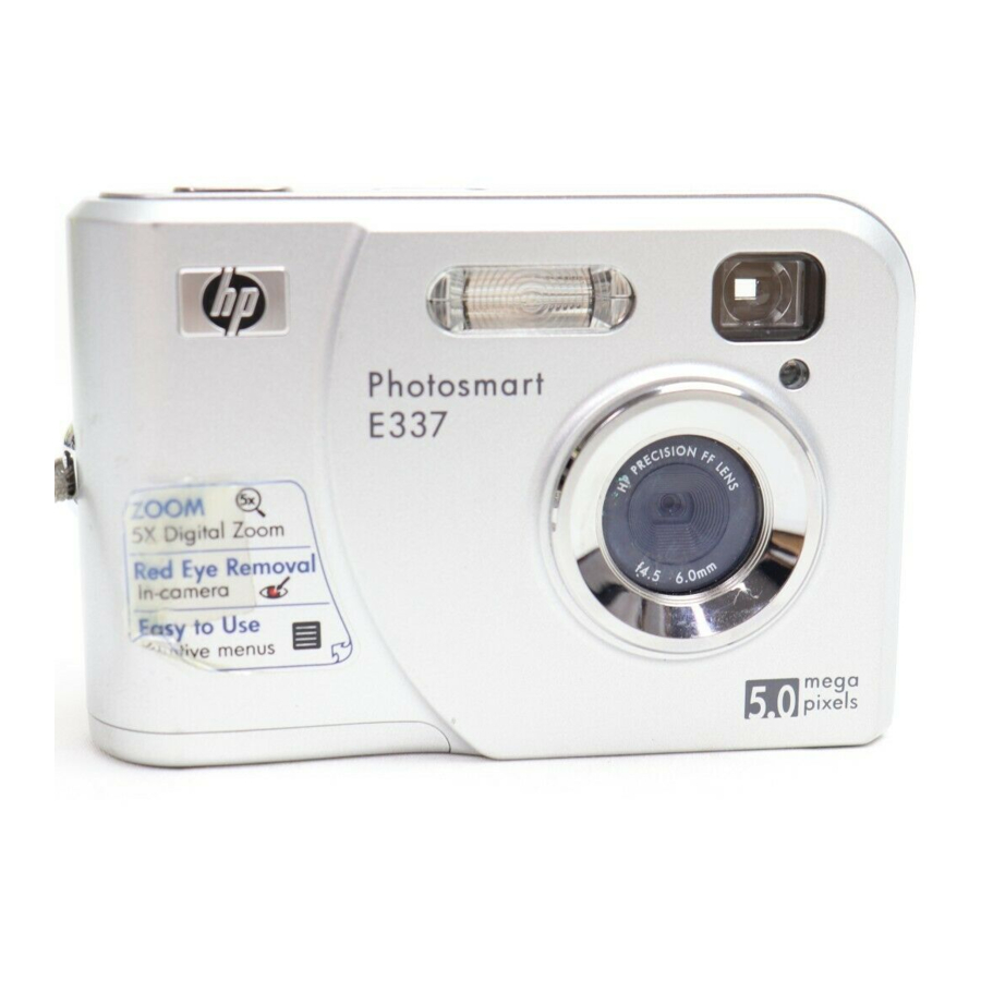
HP E337 MODIFICATION
www.bfoutdoors.com
BFoutdoors assumes no responsibility for personal injury or property damage
resulting from these modifications. Furthermore, modification of commercial
products is done at your own risk, and can result in permanent fatal damage to
the camera if not properly done. Please use extreme caution since high voltage
exists within camera flash units. Take proper steps to assure all energy has been
discharged (from the capacitors, etc.), before touching any components inside
the camera. You should AT LEAST cover the camera lens and take a flash
picture, and then IMEDIATELY open the battery cover to prevent the flash from
recharging. Even so, there will still be some charge leftover that might shock
you, or destroy the camera if shorted somewhere!
Before beginning this hack, you need to remove the batteries and memory card
from the camera...and save the refreshments for celebration afterwards
:)
The first step will be to remove the 6 screws on the underside of the camera, one
of them is hiding deep down inside the battery compartment, and it actually holds
the Shutter/Power board in place.
Advertisement
Table of Contents

Subscribe to Our Youtube Channel
Summary of Contents for HP E337
- Page 1 HP E337 MODIFICATION www.bfoutdoors.com BFoutdoors assumes no responsibility for personal injury or property damage resulting from these modifications. Furthermore, modification of commercial products is done at your own risk, and can result in permanent fatal damage to the camera if not properly done. Please use extreme caution since high voltage exists within camera flash units.
- Page 2 The Shutter /Power cover plate needs be removed, or taken off. Start by prying the bottom edge out with a fingernail, then use a small screwdriver to pry it out of a snap lock of sorts, holding it on about halfway up the left side. Now you slide the Power/Shutter plate off.
- Page 3 You will now see there are 3 more screws you have to remove, 2 on the side, where the Power/Shutter plate covered them, and one on the top of the camera. I have already removed the one on top, but it was in the corner where I circled. After removing these next 3 screws, you can finally take the front section off of the camera.
- Page 4 The back case should come right off now, and we can get to main board. Using an ISO setting of 400 makes for much better night pictures, and I feel this is needed. I found that when we set this camera to sports mode, it will go to ISO 400, but when we power it off, it returns back to the default setting of ISO 200.
- Page 5 Now peel back the protective foil covering the top right back edge of this board, and solder the power and shutter control wires as shown. When routing the wires out, take care so that they won’t interfere with any of the buttons and switches on the board.
- Page 6 As I said we run a 4-wire connector at the camera, here is where I installed it. On the controller board side we will join the RED power and menu wires, so that when connected to the controller, the camera will always turn on in ACTION Mode, and keep the ISO 400 setting.
- Page 7 Camera Settings and setup Most settings will be the default settings there are only 2 that will help. 1. Turn the camera on and press the menu button. Scroll through the options and there is one that allows us to make the LCD screen darker. Since it can’t be turned off this is a valuable power savings option.


Need help?
Do you have a question about the E337 and is the answer not in the manual?
Questions and answers