Advertisement
Available languages
Available languages
Quick Links
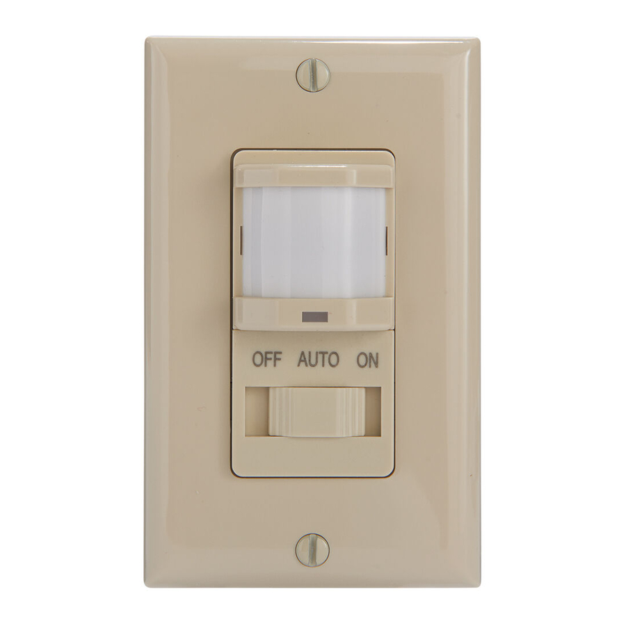
MODEL: IOS-DSIMF/IOS-DPBIMF
Ratings:
SCR contained, not suitable for use with electronic ballast
Incandescent / Tungsten: 500W-120VAC
Motor: 1/8HP-120VAC
Time Delay: 15 Sec to 30 Min
Light Level: 30 Lux--Daylight
Operation Temperature: 32˚F--131˚F / 0-55˚C
Minimum Load: 25W
INSTALLATION INSTRUCTIONS
Description:
The passive infrared sensors work by detecting the difference between heat emitted from the human body in motion and the
background space. The sensor switch can turn a load ON and hold it as long as the sensor detects occupancy. After no motion is
detected for the set time delay, the load turns OFF automatically. The sensor switch has one relay (equal to single pole switch), it
also includes Ambient Light Level Sensor.
Coverage Area:
The coverage range of the sensor switch is specified and illustrated in Figure 1. Large objects and some transparent barriers like
glass windows will obstruct the sensor's view and prevent detection, causing the light to turn off even though someone is still in
the detection area.
LOCATION/MOUNTING
Since this device responds to temperature changes, care should be taken when mounting the device.
DO NOT mount directly above a heat source, in a location where hot or cold drafts will blow directly on the
sensor, or where unintended motion will be within sensor's field-of-view.
INSTALLATION
1. Connect lead wires as shown in WIRING DIAGRAM (see Figure 2): Black lead to Line (Hot), Red lead to Load
wire, Green lead to Ground.
2. Gently position wires in wall box, attach sensor switch to the box.
3. Mount device "TOP" up.
4. Restore power at circuit breaker or fuse, wait one minute.
5. Remove the small cover plate. (Illustrated as Figure 3.)
6. Locate the adjustment knobs on the control panel to perform test and adjustments.
(Illustrated as Figure 4.)
7. Replace the small cover plate after testing and adjusting.
8. Attach the wallplate.
NOTE: If twist on wire connector is provided, use to join one supply conductor with one 16 AWG device control
lead.
ADJUSTMENT
Time Delay Knob
Default position: 15 Seconds (Test mode)
Adjustable: from 15 Seconds to 30 Minutes (clockwise)
Sensor Sensitivity Range Knob
Default position: Center at 65%
Adjustable: 30% (Position 1) to 100% (Position 4)
Note: Turn clockwise for larger rooms. Turn counter clockwise to avoid false alerts in smaller rooms or
near doorway or heat source.
Ambient Light Level Knob: Default position: Daylight (100% at position 4)
Adjustable: Daylight to 30 Lux (Counter clockwise)
OPERATION
Band Switch
Mode
Position
Description
OFF
LEFT
Circuit is permanently opened (switched off)
AUTO
Center
Occupancy Mode:
Automatic ON when occupancy is detected.
Automatic OFF after the set time delay.
ON
RIGHT
Load stays ON always.
Push-button:
As illustrated in Figure 5, the Load stays OFF when the button is pushed in and locked. (switched Off) As illustrated in Figure 6,
the Load turns ON after the button is pressed and released. The sensor switch stays at the OCC Mode until the button is pressed
OFF next time.
IOS-DPBIMF
IOS-DSIMF
WARNING
Risk of Fire, Electrical Shock or Personal Injury
• Turn OFF power at circuit breaker or fuse and test that the power is OFF before wiring.
• To be installed and/or used in accordance with appropriate electrical codes and regulations.
• If you are not sure about any part of these instructions, consult a qualified electrician.
• Use this device only with copper or copper clad wire.
INDOOR USE ONLY
•
Neutral
White
Hot
Black
Ground
Green
Occupancy
Sensor Switch
Maximum: 980 sq.ft.
150˚ Field of View
Wiring Diagram
Neutral
White
Hot
Load
LOAD
Red
Black
Neutral(White)
Ground
Green
Figure 2
IOS-DSIMF
IOS-DPBIMF
Top View
18'
9'
9'
18'
Side View
5'
4'
15'
30'
Figure 1
Load
LOAD
Red
Neutral(White)
Figure 3
Figure 4
Press
(Lock)
OFF
Figure 5
Press and release
AUTO
Figure 6
Advertisement

Related Manuals for Intermatic IOS-DSIMF


Summary of Contents for Intermatic IOS-DSIMF
- Page 1 Occupancy Sensor Switch MODEL: IOS-DSIMF/IOS-DPBIMF Ratings: IOS-DPBIMF IOS-DSIMF SCR contained, not suitable for use with electronic ballast Incandescent / Tungsten: 500W-120VAC Motor: 1/8HP-120VAC WARNING Risk of Fire, Electrical Shock or Personal Injury Time Delay: 15 Sec to 30 Min • Turn OFF power at circuit breaker or fuse and test that the power is OFF before wiring.
- Page 2 Presencia Interruptor MODELO: IOS-DSIMF/IOS-DPBIMF Sensor Capacidades: IOS-DPBIMF IOS-DSIMF SCR contenido, no apropiado para uso con balasto electrónico Incandescente / Tungsteno: 500W-120VCA ADVERTENCIA Motor: 1/8HP-120VCA Riesgo de incendio, descarga eléctrica o lesiones personales Retardo: De 15 seg. a 30 min. • A PAGAR la electricidad en el disyuntor o fusible y corroborar que la electricidad esté APAGADA antes de realizar el cableado.
- Page 3 Occupation Contacteur MODÈLE : IOS-DSIMF/IOS-DPBIMF de détection Puissances nominales : IOS-DPBIMF IOS-DSIMF Contient du RCS, ne convient pas pour les ballasts électroniques Incandescent /Tungstène : 500 VA - 120 V c.a. Moteur : 1/8 HP à 120 V c.a AVERTISSEMENT Risque d’incendie, d’électrocution ou de blessure corporelle Temporisateur : 15 s à...
- Page 4 This warranty service is available by either (a) returning the product to the dealer from whom the unit was purchased, or (b) completing a warranty claim on line at www.intermatic.com. This warranty is made by: Intermatic Incorporated, Customer Service 7777 Winn Rd.
Need help?
Do you have a question about the IOS-DSIMF and is the answer not in the manual?
Questions and answers