Table of Contents
Advertisement
Quick Links
Advertisement
Table of Contents
Troubleshooting

Related Manuals for FLETCHER FSC 65


Summary of Contents for FLETCHER FSC 65
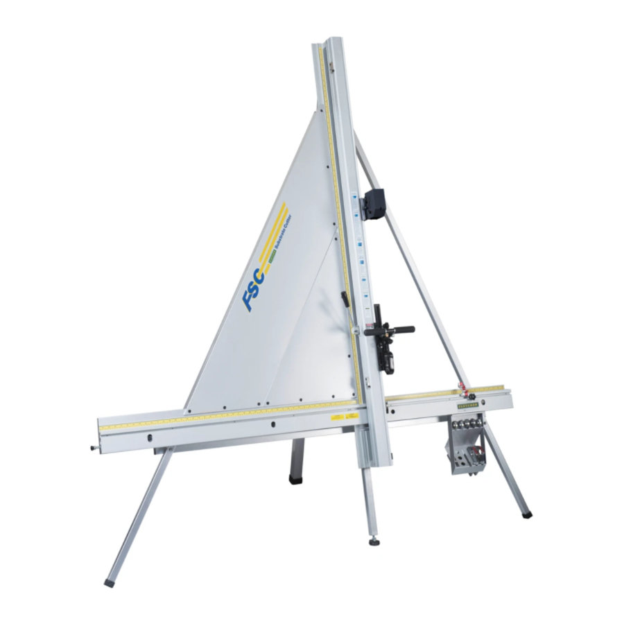
- Page 1 Fletcher-Terry FSC 65" Substrate Cutter Instruction Manual...
- Page 2 OWNER’S MANUAL Fletcher Substrate Cutter (FSC) The Fletcher-Terry Company 65 Spring Lane • Farmington, CT USA 06032-3311 Tel 860.677.7331 • Toll-Free 888.888.5165 • Fax 860.676.8858 • customerservice@fletcher-terry.com • www.fletcher-terry.com FORM ENG‐033109 ...
-
Page 3: Table Of Contents
INTRODUCTION ............................PRODUCT WARRANTY ........................SAFETY FIRST .............................. INSTALLATION 1. Unpacking the FSC A. Contents Include ......................... 1 B. Hardware List ........................2 2. Terminology for Set-Up ......................3 3. Pre-Assembly ..........................3 4. Positioning the Vertical Track Assembly ................... 4 5. - Page 4 USING CUTTING TOOLS AND SUBSTRATES 25. Cutting Blades and Wheels A. ¼" (7mm) Blade Holder (optional) ................... 16 B. ½" (13mm) Blade Holder ....................16 C. Acrylic Blade Holder ......................16 D. Glass Scoring Wheel Holder (optional) ................16 E.
- Page 5 ........ 34 NOTE: Our Replacement Parts List and Schematics are in the final stages and will be posted on our website (www.fletcher-terry.com) when they become available. In the meantime, if you need technical support, contact our customer service department at: 800.843.3828 (in the United States)
-
Page 6: Introduction
The Fletcher-Terry Company does not authorize any company employee or representative to assume for it any other liability than that set forth in this Product Warranty. The Fletcher- Terry Company shall not be liable for any damages or losses, whether incidental or consequential or direct or indirect, arising out of the use or abuse of this machine. -
Page 7: Safety First
SAFETY FIRST! Please read through this manual before operating the Fletcher Substrate Cutter (FSC). If after reviewing these pages you still have questions about using the machine, contact our Customer Service Department toll-free at 1.800.843.3826 in the United States. Outside the United States, call ++860.677.7331 or email customerservice@fletcher-terry.com. -
Page 8: Installation
Installation Installation of the FSC Unpacking the FSC Check the exterior of the packing box to make sure there is no visible damage. After unpacking the unit, check to make sure all the parts are present and undamaged. Contents Include •... -
Page 9: Hardware List
Installation B. Hardware List B V U S R L T Item Hardware Description Assembly Section M10 x 25mm Hex Head Bolt Rear Leg to Rear Mounting Bracket M10 Sleeve Rear Leg to Rear Mounting Bracket M10 x 50mm Hex Head Bolt Center Adjustable Leg M10 Hex Lock Nut Center Adjustable Leg... -
Page 10: Terminology For Set-Up
Installation ♦ Notes: • To assemble the FSC, you will need a cleared workspace approximately 10'x10'. • All views mentioned for the assembly of the FSC are from the perspective of the customer facing the standing machine. • All bolts are inserted from left-to-right, or from front-to-back. Terminology for Set-Up The Vertical Track Assembly has been assembled for you. -
Page 11: Positioning The Vertical Track Assembly
Installation Positioning the Vertical Track Assembly Parts Needed: Tools Two boxes approximately the same height Tip: You can use the Tool Caddy Box and the Laser Box included with the FSC as supports. Lift the Vertical Track Assembly out of the box, and place it on the workroom floor. CAUTION: To protect against personal injury, two people should lift the pre-assembled unit. -
Page 12: Connecting The Rear Leg (Wall-Mount Only)
Installation Connecting the Rear Leg (Wall-Mount Only) Parts Needed: Frame Parts Qty. Hardware Tools Needed See Pg 2 Rear Leg M8 x 70mm Button Head Screw 5mm Hex Key (Top and Bottom) M8 Flat Washer 13mm Wrench M8 Hex Lock Nut Slide the bottom portion of the Rear Leg onto the top portion. -
Page 13: Attaching The Horizontal Brace Channel
Installation Attaching the Horizontal Brace Channel Parts Needed: Frame Parts Qty. Hardware Tools Needed See Pg 2 Horizontal Brace Channel M6 x 20mm Flat Head Screw 4mm Hex Key (Page 1 - #7) Horizontal Brace Locate the two (2) holes at the bottom, right-hand side of Channel the Vertical Track Assembly as viewed from the back of the machine (see Figure on the right). -
Page 14: Assembling The Right Leg And The Rear Horizontal Brace
Installation Assembling the Right Leg and the Rear Horizontal Brace Parts Needed: Frame Parts Qty. Hardware Tools Needed See Pg 2 Right Leg Bottom M8 x 80mm Socket Cap Screw 6mm Hex Key (Page 1 - #4) M8 Flat Washer M8 Hex Lock Nut Rear Horizontal Brace M8 x 50mm Button Head Screw... -
Page 15: Connecting The Rear Leg (Free-Standing Unit Only)
Installation Connecting the Rear Leg (Free-Standing Unit Only) Parts Needed: Frame Parts Qty. Hardware Tools Needed See Pg 2 M10 x 25mm Hex Head Bolt 5mm Hex Key M10 Sleeve 13mm Wrench Lower Rear Leg M8 x 70mm Button Head Screw M8 Flat Washer M8 Hex Lock Nut Insert two (2) M10 Bolts with two (2) Sleeves to... -
Page 16: Preparing The Fsc For Wall-Mounting (Wall-Mounted Unit Only)
Installation Preparing the FSC for Wall-Mounting (Wall-Mounted Unit Only) Parts Needed: Frame Parts Qty. Hardware Tools Needed See Pg 2 M10 x 25mm Hex Head Bolt Carpenter’s Level M10 Sleeve Insert the two (2) M10 Bolts with Sleeves into the top most holes on either side of the Vertical Track Assembly. -
Page 17: Mounting The Face Plates
Installation Mounting the Face Plates Parts Needed: Frame Parts Qty. Hardware Tools Needed See Pg 2 Small Face Plate M6 x 20mm Flat Head Screw 4mm Hex Key (Page 1 - #8) M6 x 12mm Button Head Screw Large Face Place M6 Flat Washer 10mm Wrench... -
Page 18: Securing The Face Plate To The Left Frame Leg
Installation Securing the Large Face Plate to the Left Frame Leg Parts Needed: Hardware Tools Needed M6 x 40mm Button Head Screw 3mm Hex Key (was attached to Bracket “P’) 8mm Wrench Insert the M6 x 40mm Button Head Screw, M6 Flat Washer, and M6 Hex Nut that came with the Bracket to secure the Large Face Plate to the Left Leg. Tighten the Screw using a 3mm Hex Key and 8mm Wrench. -
Page 19: Securing The Wall-Mounted Unit (Wall-Mounted Unit Only)
Installation Insert the one (1) M8 x 110mm Socket Cap Screw and two (2) Flat Washers through the Horizontal Material Bar and secure the one (1) Lock Nut using a 6mm Hex Key and 13mm Wrench. ♦ Note: Rotate the Spacer until it is flush with the Right Leg. (Free-Standing Unit assembly continues at “Inserting the Production Stops”... -
Page 20: Mounting The Tool Caddy
Installation Mounting the Tool Caddy Parts Needed: Frame Parts Qty. Hardware Tools Needed Screws Tool Caddy Phillips-head Screwdriver Washers (packed with Tool Caddy) Locate the two (2) holes under the right side of the Horizontal Material Bar. Align the holes on the top of the Tool Caddy with the holes under the right side of the Horizontal Material Bar. -
Page 21: Setting The Scales
Installation Setting the Scales Install a Blade Holder into the FSC. Install the Production Stops. Loosen the right (larger) Production Stop Knob, slide onto the front of the Horizontal Material Bar from the right and tighten the Knob. Repeat with the other Production Stop, sliding it onto the left side. - Page 22 Installation Lower the Clamp Lever fully so that the stationary part and the moveable clamp are firmly together. To verify clamping, attempt to remove the folded paper. If the paper cannot be removed, the center stationary part and moveable clamp have proper clamping. If the paper can be pulled out, adjust both the bottom and top eccentrics to provide proper clamping for this area.
-
Page 23: Ii. Using Cutting Tools And Substrates
Cutting Tools and Substrates II. Using Cutting Tools and Substrates Cutting Blades and Wheels ♦ Note: Using the Blade Holder that is appropriate for the thickness of your material will minimize the possibility of blade deflection. the possibility of blade deflection. ¼"... -
Page 24: Installing New Cutting Blades/Wheels/Scoring Tips Into Holders
Cutting Tools and Substrates Installing New Cutting Blades/Wheels/Scoring Tips into Holders CAUTION: Blades are extremely sharp. Handle with care. ½" (13mm) or ¼" (7mm) Blade 1. Loosen the Blade Clamp Screw on the Blade Holder using a Phillips-head Screwdriver. 2. -
Page 25: Cutting Techniques For Various Substrates
Cutting Tools and Substrates Glass Scoring Wheel 1. Position the new Glass Scoring Wheel in the gap so the notch is positioned inward. 2. Gently rock it back-and-forth until it is firmly seated into place. Cutting Techniques for Various Substrates Each material you will use has its own unique characteristics. -
Page 26: Scoring And Breaking Techniques For Fracture-Sensitive Material
Cutting Tools and Substrates ♦ Notes: • Production Stop should be used if making more than one piece of the same size. Thinner materials can be cut with one pass, but thicker materials will • take more than one pass to cut through material. Scoring and Breaking Techniques for Fracture-Sensitive Material ♦... -
Page 27: Proper Glass Scoring And Breaking Techniques
Cutting Tools and Substrates Proper Glass Scoring and Breaking Techniques CAUTION: Always wear eye protection, gloves, and protective clothing when handling glass. Always load glass from the left side of the machine. Glass should not extend beyond the edges of the Horizontal Material Bar. Always score in a downward stroke. -
Page 28: Operating The Fsc
Operating the FSC III. Operating the FSC Inserting the Cutting Tool in the Cutting Head Raise the Cutting Head to a comfortable level by grabbing either the Dual Handle Bar, or the black Handle. Hold the Cutting Tool so the Blade Screw is to your right. Insert the Blade Holder so the small tab on the left side of the Blade Holder is positioned in the notch of the Cutting Head above the Dual Handle Bar. -
Page 29: Using The Production Stops
Operating the FSC Using the Production Stops ♦ Note: Always use the Silver Stop Levers Fingers with the Blade Holders, and the Red Stop Levers Fingers with the Wheel Holders. Unscrew the black Locking Knob. Slide the Production Stops to the desired location. Tighten the Locking Knob to secure the position. -
Page 30: Locking The Rocker Arm
Operating the FSC Locking the Rocker Arm The Rocker Arm Locking Pin secures the Blade in the cutting position. This ensures a consistent cut. It is recommended that the Rocker Arm Locking Pin be enabled on all final cutting passes. To Lock 1. -
Page 31: Iv. Installing The Laser
Maintenance, Adjustments, Troubleshooting and FAQ IV. Installing the Laser Setting Up the Laser Tools Needed: Tools Needed 10mm, 16mm, 17mm Wrenches 2mm, 2.5mm, 4mm 1/8" Hex Keys 1. Loosen the black Handle by turning Laser Mount Four Set Screws it counterclockwise. 2. Slide the Laser all the way to the left along the Laser Shaft. -
Page 32: Dual Position Laser
Maintenance, Adjustments, Troubleshooting and FAQ Dual Position Laser ♦Note: The FSC cutting tool holders are sized for cutting performance. The “wheeled” tools are larger and provide an off-set cut line compared to the blade tool. The Laser Assembly is designed with a Dual Position feature giving you the ease of positioning the Laser Sight-Line to ... -
Page 33: Positioning The Laser For Use With The Wheel
Maintenance, Adjustments, Troubleshooting and FAQ Place the Cutting Head at the top of the substrate and make a cut approximately 1" (2.5 mm) in length. Remove the Aluminum Composite Wheel and return the Cutting Head to its resting position at the bottom Vertical Track Assembly. - Page 34 Maintenance, Adjustments, Troubleshooting and FAQ If the beam falls across your substrate from top left to bottom right, use a 2mm Hex Key to: 1. Tighten the bottom Set Screw and the beam will move to the right. When it is positioned over the top of the score line, stop tightening.
-
Page 35: Securing The Blade Cutting Laser Position
Maintenance, Adjustments, Troubleshooting and FAQ Securing the Blade Cutting Laser Position Place a 2.5mm Hex Key in the brass-tipped Set Screw located on the top, left-hand side of the Laser Assembly, and a 10mm Wrench on the Hex Nut opposite the Screw. Tighten the Screw to create the Blade Cutting Laser Position. -
Page 36: Maintenance, Adjustments, Troubleshooting & Faq
Maintenance, Adjustments, Troubleshooting & FAQ V. Maintenance, Adjustments, Troubleshooting & FAQ General Maintenance Tips Cleaning With care and frequent cleaning, the FSC will remain in proper working order, and will perform indefinitely, as expected. 1. Clean the Horizontal Support Material Extrusion. If debris collects on the Bar, the substrate will not sit squarely, and will not cut straight. -
Page 37: Replacing The Cutting Head Bearings
Maintenance, Adjustments, Troubleshooting & FAQ 2. Using the 3mm Hex Key Wrench, turn both Screws clockwise in increments of about one-eighth (1/8) of a revolution (see Figure on the right). 3. Check to see if the bearings are no longer loose by sliding the Cutting Head Assembly up and down the Vertical Track Assembly. -
Page 38: Troubleshooting Your Fsc
If this Troubleshooting Guide or the Frequently Asked Questions listed below does not answer your questions, call our Customer Service Department at 1.800.843.3826 (within the United States) or outside the United States, call ++800.843.3826, visit our website (www.fletcher-terry.com) or send an email to customerservice@fletcher-terry.com. -
Page 39: Frequently Asked Questions
Maintenance, Adjustments, Troubleshooting & FAQ Frequently Asked Questions VII. A. Materials Q: What is the best way to cut corrugated plastic? A: When cutting across corrugated plastic flutes, cut in a single pass. When cutting in the direction of the flutes, position the blade between the flutes to avoid blade deflection. -
Page 40: Cutting
Q: How long do the blades and wheels last? All Fletcher cutting blades and wheels are “Extended Life” blades/wheels. The life of the A: cutting edge is directly correlated to the type of material being cut. For instance, cutting plastic type materials (PVC, corrugated plastics, etc.) tend to self-hone the edge, and will... -
Page 41: Replacement Parts List And Schematics
VI. Replacement Parts List & Schematics NOTE: Our Replacement Parts List and Schematics are in the final stages and will be posted on our website (www.fletcher-terry.com) when they become available. In the meantime, if you need technical support, contact our customer service department at: 800.843.3828 (in the United States)
Need help?
Do you have a question about the FSC 65 and is the answer not in the manual?
Questions and answers