
Related Manuals for EM Acoustics S-18


Summary of Contents for EM Acoustics S-18
- Page 1 S-18 Subwoofer Product User Manual v2 November 2019 L O U D S P E A K E R S D E F I N E D...
-
Page 2: Table Of Contents
Rigging and Suspension ........................9 Material Damage from Magnetism ....................9 5.0 – Rigging Options ........................... 10 5.1 – S-18 Cabinet Hardware Overview ................... 10 5.2 – Stacking S-18 subwoofers......................11 5.3 – Using the M20 threaded pole adapter ................... 12 5.4 –... - Page 3 6.4.3 – Crossover Cable Use ......................21 7.0 – Servicing Information ........................22 7.1 – S-18: Removing the grille ......................22 7.2 – S-18: Removing the drive unit ....................23 Appendix A – Technical Specifications ....................24 S-18 compact reflex subwoofer ......................24 Appendix B –...
-
Page 4: Declaration Of Conformity
The packaging supplied with this product is recyclable. Please retain all packaging, however if disposing of this packaging please ensure that you comply with local recycling regulations. These products also all comply to the RoHS Directive 2002/95/EC. S-18 User Manual v2 November 2019... -
Page 5: Introduction
EM Acoustics representative. The S-18 is a high-power compact reflex subwoofer, intended for a wide variety of low frequency applications in medium to large applications. The S-18 is equally at home in permanent installations as well mobile applications due to its rugged construction. -
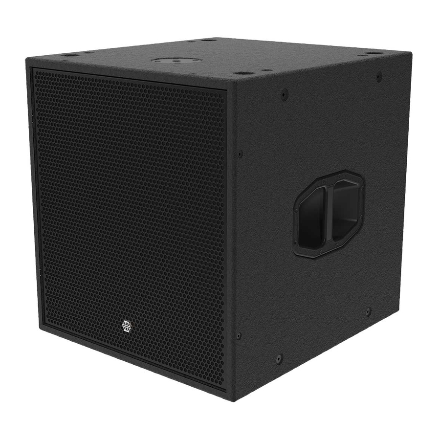
Page 6: S-18 Subwoofer
S-18 Compact high-power reflex subwoofer FEATURES & BENEFITS • Signature EM Acoustics “maximum headroom” design approach ensures consistency of performance regardless of SPL level. • Integral M20 theaded pole adapter for mounting of fullrange loudspeakers. • Multiple M10 threaded flying points for temporary and permanent installation. -
Page 7: Simulation
Tutorials for Ease Focus 3 are available from with the application itself. For training on the design and implementation of S-18 subwoofers including the specific use of Ease Focus 3, please contact your local distributor. -
Page 8: Safety Considerations
General Considerations in use Loudspeaker systems are potentially dangerous objects if used incorrectly. Please ensure that you read this section fully, and contact EM Acoustics or your local dealer should you be in any doubt over correct operation procedures. Personal Injury Never stand in the immediate vicinity of loudspeakers when in use at high level. -
Page 9: Rigging And Suspension
Larger distances may be required for some older cathode ray tube displays. S-18 User Manual v2 November 2019... -
Page 10: Rigging Options
Page 10 of 27 5.0 – Rigging Options 5.1 – S-18 Cabinet Hardware Overview Lifting & Carrying Handle M20 threaded pole adapter Rubber foot Stacking recess M10 threaded flying point Castor attachment point S-18 User Manual v2 November 2019... -
Page 11: Stacking S-18 Subwoofers
Page 11 of 27 5.2 – Stacking S-18 subwoofers The S-18 subwoofer has four rubber feet on the underneath, and matching recesses in the top face of the cabinet. When stacking S-18 subwoofers, this provides a neat and clear way of creating a tidy stack. -
Page 12: Using The M20 Threaded Pole Adapter
Page 12 of 27 5.3 – Using the M20 threaded pole adapter The S-18 has an M20 threaded adaptor in the top face, designed to receive M20 threaded pole fittings such as the EM Acoustics DP-01 or DP- 02. To fit such a device, carefully start the... -
Page 13: Flying The S-18 Subwoofer
M10 bolts on the cabinet where you will be attaching your chosen suspension method. Any of the S-18 points can be used for suspension. Due to the location of points and the centre of gravity of the loudspeaker, it is strongly advised to use four points to suspend the loudspeaker as shown below to ensure the subwoofer sits straight. -
Page 14: Fitting Castors
Page 14 of 27 5.5 – Fitting castors The S-18 is supplied with a set of four tour-grade castors which can be fitted for ease of movement. The carton should contain: 4pcs 32 x 100mm heavy duty castor 17pcs M8 x 30 hex head set screw... -
Page 15: Cardioid Use
Page 15 of 27 5.6 – Cardioid Use The S-18 feet and recess locations are symmetrical front-to-back, so subwoofers can be reversed to create cardioid arrays. Simply assemble the subwoofer stack or flown column as normal but reverse every third subwoofer. The stack of subwoofers should be secured with ratchet straps or similar for safety. -
Page 16: Powering The System
6.1 - Amplifier and Processing Requirements 6.1.1 - Connections The S-18 requires only a single amplifier channel. Inputs to the S-18 enclosure are on Neutrik SpeakON NL4 as illustrated below. Two-core cable should be used for connecting S-18 subwoofers, and the connections are... -
Page 17: Amplifier Requirements
Max S-18 per channel DQ10 DQ20 * - The DQ6 does not provide sufficient power for maximum headroom for the S-18 and as such should only be used in lower SPL environments. 6.1.4 – Processing Requirements The S-18 requires active high and low pass filters, and appropriate limiter settings. If not using DQ Series amplifiers, or the DSC48 Digital System Controller, then a suitable DSP system must be used in conjunction with your S-18 to prevent damage to the subwoofer. -
Page 18: Presets And Settings
6.2.2 – Cardioid Array Preset The S-18 can be used to create cardioid arrays by ensuring that one in three S-18 subwoofers are physically reversed, and the appropriate S-18 Cardioid preset is loaded into the amplifier. This preset requires three amplifier channels, and with a DQ20 amplifier can power up to two S-18 subwoofers per amplifier channel. -
Page 19: Geometric Delay
The presets are intended to be a starting point for your system and will almost certainly require tuning on-site dependent on room characteristics, the rest of your system design and the system voicing you are aiming for. The S-18 is designed with a significant amount of system headroom, so applying EQ is perfectly acceptable. -
Page 20: Use With The Dq Series Advanced System Amplifiers
Page 20 of 27 6.3 - Use with the DQ Series Advanced System Amplifiers The S-18 will perform best when using DQ Series advanced system amplifiers, as not only are they state-of-the-art amplifiers, but the onboard DSP provides appropriate high/low pass filter settings and limiters to get the best from your subwoofers. -
Page 21: System Connectivity
Because pins 2+/2- are linked through inside all EM Acoustics loudspeakers, using a 4-core cable to one loudspeaker (carrying two different signals) allows a crossover cable to be used to link out of the first loudspeaker into another, thereby feeding it from a separate signal. -
Page 22: Servicing Information
Page 22 of 27 7.0 – Servicing Information All S-18 components can be removed for service purposes if required, using the minimum of tools. 7.1 – S-18: Removing the grille TOOLS REQUIRED: 4mm Allen key Lie the enclosure on its’ back and remove the eight M6x30 countersunk socket screws using a 4mm Allen key, and then lift the grille clear of the cabinet. -
Page 23: S-18: Removing The Drive Unit
Page 23 of 27 7.2 – S-18: Removing the drive unit TOOLS REQUIRED: 5mm Allen key Complete step 7.1 above to remove the grille. Using a 5mm Allen key, remove the eight M6x40 socket cap screws that secure the drive unit. Ensure that you remove the spring washers from the recesses as well as the machine screws. -
Page 24: Appendix A - Technical Specifications
Colours/extended weather protection Accessories: TC-S18 padded transit cover * - The DQ6 does not provide sufficient power for maximum headroom for the S-18 and as such should only be used in lower SPL environments. Notes on measurement conditions: Measured on-axis at 2m in an anechoic environment and referenced to 1m. -
Page 25: Appendix B - Technical Drawings
Page 25 of 27 Appendix B – Technical Drawings S-18 User Manual v2 November 2019... -
Page 26: Appendix C - Spare Parts List
Page 26 of 27 Appendix C – Spare Parts List Order Code Description 01A022 DU-1802 replacement 4 ohm 18” LF drive unit 04A036 RFG-S18 replacement grille/fabric for S-18 S-18 User Manual v2 November 2019... -
Page 27: Appendix D - Warranty Information
Serial numbers must be quoted in all correspondence relating to the claim. EM Acoustics or its representatives are in no way liable for any loss or damage in transit, and hence it is recommended that the sender insure the shipment. EM Acoustics will pay for return freight should the repair be covered under warranty.
Need help?
Do you have a question about the S-18 and is the answer not in the manual?
Questions and answers