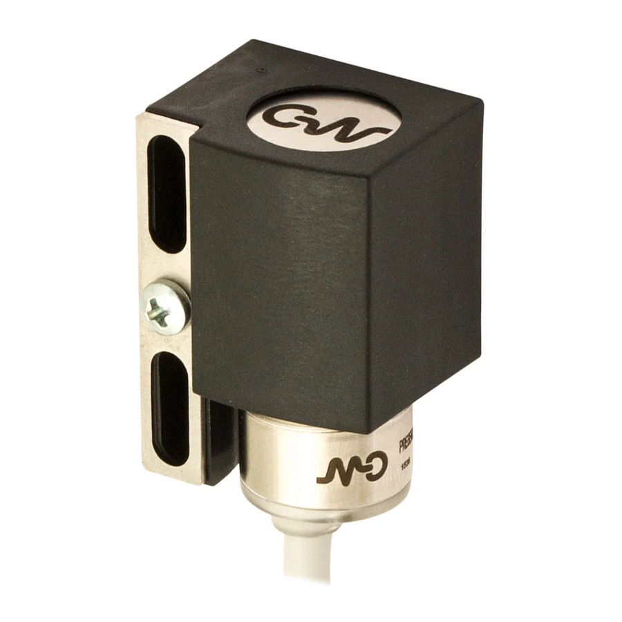
Summary of Contents for Micro Detectors VBR Series
- Page 1 Quick guide VBR Series www.microdetectors.com MD Interface download area: Host: 82.85.138.194 MDuserVBR User: MDvibrations Password: Port:...
- Page 2 USB – Serial RS485 Adapter To connect VBR sensor to a computer, it is possible to use any USB to Series converter, as for example US-324 Brainboxes. Install the driver US-324 Check if the device is correcly installed (1) Select PORT (COM e LPT) /Brainboxes.
- Page 3 Device choice Select the device (Tab. 1) : VBR VBR series INC INC Series (not included in this guide)
- Page 4 Description: TAB 1: Information regarding inclination and 3D position. COM Port Node Selection Selection TAB 2: Information regarding the 3-axis acceleration and data post processing. Fast Fourier Reference Toggle for Transform View Axis for FFTY Data Acquisition Acceleration Values...
- Page 5 TAB 3: Configuration. Sensor Parameters Upload from Sensor’s Saving of Parameters Memory of Configuration on Sensor’s Memory Parameters TAB 4: Direct command serial configuration. Serial commands Section Command Sent Characters Received...
-
Page 6: Parameters Configuration
Parameters configuration 1) Sensor node number assignment (default = 0). In case of more sensors on the same bus, each sensor must have a different node number. 2) Minimum duration (in ms) of the acceleration that generate an alarm signal. 128 different levels can be selected with a step of 2,5ms. - Page 7 OFF no output alarm. RED led is no but no alarm signal is transmitted on analogue output or BUSRS485 ON485 alarm signal only on RS485 ON ANALOG alarm signal only on analogue output ON485 + ANALOG ...
- Page 8 Curves 1) X axis selection 2) Y axis selection 3) Z axis selection NOTE: click with the mouse on the symbol to select: color, visibility, … 4) Record of the data transmitted on BUS RS485 5) FFT mode (WARNING: only for indication, not to be used for analysis) 6) FFT curve axis 7) Curves management: window, …...


Need help?
Do you have a question about the VBR Series and is the answer not in the manual?
Questions and answers