
Related Manuals for cytiva Monitor UVis-920


Summary of Contents for cytiva Monitor UVis-920
- Page 1 Monitor UVis-920 Operating Instructions Original instructions Translation disc included cytiva.com...
- Page 2 Page intentionally left blank...
-
Page 3: Table Of Contents
Maintenance ....................... 62 Cleaning before planned service ......................63 Cleaning the instrument housing ......................64 Cleaning the flow cell and optical connectors ..................65 Storage ................................67 Troubleshooting ....................68 Problems and corrective actions ......................69 Monitor UVis-920 Operating Instructions 29055049 AF... - Page 4 Евразийский экономический союз ....................82 8.3.4 Regulations for North America ....................... 84 8.3.5 Regulatory statements ..........................85 8.3.6 Declaration of Hazardous Substances (DoHS) ................86 Ordering information ........................... 88 Health and Safety Declaration Form ...................... 91 Monitor UVis-920 Operating Instructions 29055049 AF...
-
Page 5: Introduction
1 Introduction Introduction About this chapter This chapter contains important user information, descriptions of safety notices, regu- latory information, intended use of the Monitor UVis-920 instrument, and lists of asso- ciated documentation. In this chapter Section See page About this manual... -
Page 6: About This Manual
Typographical conventions Software items are identified in the text by bold italic text. Hardware items are identified in the text by bold text. In electronic format, references in italics are clickable hyperlinks. Monitor UVis-920 Operating Instructions 29055049 AF... -
Page 7: Important User Information
Intended use of the product Monitor UVis-920 is a UV and visible light absorption monitor for use in liquid chroma- tography. Monitor UVis-920 is intended for research use only, and shall not be used in any clinical procedures, or for diagnostic purposes. Prerequisites In order to operate Monitor UVis-920 in the way it is intended: •... - Page 8 Notes and tips Note: A note is used to indicate information that is important for trouble-free and optimal use of the product. Tip: A tip contains useful information that can improve or optimize your proce- dures. Monitor UVis-920 Operating Instructions 29055049 AF...
-
Page 9: Associated Documentation
System-specific documentation In addition to the Operating Instructions manual, the documentation package supplied with Monitor UVis-920 also includes one or more Product Documentation binders containing detailed specifications and traceability documents. The most important documents in the documentation package, with regard to tech- nical aspects of Monitor UVis-920, are listed in the table below. -
Page 10: Safety Instructions
This chapter describes safety precautions, labels and symbols that are attached to the equipment. In addition, the chapter describes emergency and recovery procedures, and provides recycling information. In this chapter Section See page Safety precautions Labels Emergency procedures Monitor UVis-920 Operating Instructions 29055049 AF... -
Page 11: Safety Precautions
2.1 Safety precautions Safety precautions Introduction Monitor UVis-920 is powered by mains voltage and handles materials that can be hazardous. Before installing, operating or maintaining the system, you must be aware of the hazards described in this manual. Follow the instructions to avoid injury to the operator or other personnel, damage to samples or other substances handled by the equipment, to the product, or to other equipment in the area. - Page 12 Access to power switch and power cord with plug. Do not block access to the power switch and power cord. The power switch must always be easy to access. The power cord with plug must always be easy to disconnect. Monitor UVis-920 Operating Instructions 29055049 AF...
- Page 13 Maintenance WARNING Electrical shock hazard. All repairs should be done by service personnel authorized by Cytiva. Do not open any covers or replace parts unless specifically stated in the user documentation. WARNING Disconnect power. Always disconnect power from the instru- ment before performing any maintenance task.
- Page 14 2 Safety instructions 2.1 Safety precautions WARNING Use only approved parts. Only spare parts and accessories that are approved or supplied by Cytiva may be used for maintaining or servicing the product. WARNING Corrosive substance. NaOH is corrosive and therefore dangerous to health.
-
Page 15: Labels
Code no Instrument assembly number Serial no Instrument serial number Mfg Year Year (YYYY) and month (MM) of manufacture Voltage Electrical requirements: Frequency • Voltage (VAC Max Power • Frequency (Hz) • Max. power (VA) Monitor UVis-920 Operating Instructions 29055049 AF... -
Page 16: Emergency Procedures
Emergency procedures Introduction This section describes how to shut down the Monitor UVis-920 instrument in an emer- gency situation, and the procedure for restarting the Monitor UVis-920 instrument. The section also describes the result in the event of power failure. -
Page 17: Instrument Description
3 Instrument description Instrument description About this chapter This chapter gives an overview of the Monitor UVis-920 instrument, and a brief descrip- tion of its function. In this chapter Section See page Instrument overview Monitor principle Flow cell principle Monitor UVis-920 Operating Instructions 29055049 AF... -
Page 18: Instrument Overview
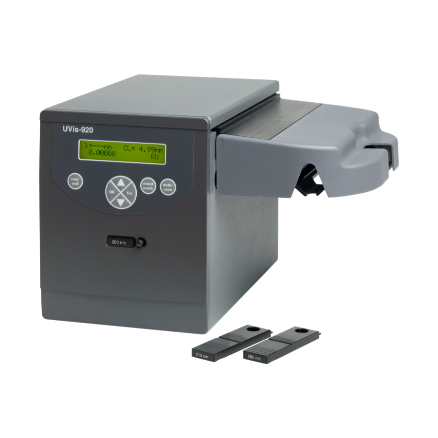
Instrument overview Introduction to Monitor UVis-920 The Monitor UVis-920 is a UV and visible light absorption monitor which can be used in wavelengths range between 200-700 nm by changeable fixed wavelength filters. The instrument contains no internal user replaceable items. - Page 19 3 Instrument description 3.1 Instrument overview Illustration of the front panel The illustration below shows the front panel of Monitor UVis-920. Part Function Eject button for filter unit OK key run/end key Display Arrow up key Arrow down key event mark key...
- Page 20 3 Instrument description 3.1 Instrument overview Illustration of the rear panel The illustration below shows the rear panel of Monitor UVis-920. Voltage 100 - 240 V Frequency 50 - 60 Hz Power max 35 VA Part Function Analog out 0-1 V. Recorder output, 1 channel 0 V to 1 V For service use only Remote.
-
Page 21: Monitor Principle
50% being directed through the reference fiber (R). Two photodiodes with identical characteristics monitor the intensities of the measuring and reference beams. The illustration below shows the monitor principle. Part Function Flash lamp 100 Hz Filter unit Beam Monitor UVis-920 Operating Instructions 29055049 AF... - Page 22 3 Instrument description 3.2 Monitor principle Part Function Interference filter monochromator Reference Micro controller Signal Optical fibres Flow cell Monitor UVis-920 Operating Instructions 29055049 AF...
-
Page 23: Flow Cell Principle
The precision of monitoring is enhanced by the construction of the flow cell, which ensures total reflectance of light. This maintains a high intensity of light to the detector. The long path length combined with a small cell volume increases sensitivity. Monitor UVis-920 Operating Instructions 29055049 AF... -
Page 24: Installation
4 Installation Installation About this chapter This chapter provides required information to enable users and service personnel to unpack, install, move and transport Monitor UVis-920. Safety precautions WARNING Before attempting to perform any of the procedures described in this chapter, you must read and understand all contents of the Safety instructions chapter. -
Page 25: Site Requirements
The instrument should not be used in a corrosive atmosphere or in an atmosphere where deposits are liable to form on the optical surfaces. Electrical power requirements Parameter Requirement Supply voltage 100-240 V~ Frequency 50/60 Hz Transient overvoltages Overvoltage category II Monitor UVis-920 Operating Instructions 29055049 AF... -
Page 26: Unpacking
• Check that all the parts are either mounted on the system or located in the acces- sory kit box. If any damage is found, document the damage, and contact your local Cytiva represen- tative. It is recommended that all packing materials should be retained if onward transport of the instrument is expected. -
Page 27: Transport
4 Installation 4.3 Transport Transport Before moving the equipment: disconnect all connected cables and tubing. Monitor UVis-920 Operating Instructions 29055049 AF... -
Page 28: Installing The Cell Holder
Step Action Unpack the cell holder. Slide the cell holder in place on the right hand side of the Monitor UVis-920 instrument. Monitor UVis-920 Operating Instructions 29055049 AF... - Page 29 4 Installation 4.4 Installing the cell holder Step Action Fasten the flow cell holder with the two screws included. Use a hex wrench. Monitor UVis-920 Operating Instructions 29055049 AF...
-
Page 30: Installing The Flow Cells
In this section Section See page 4.5.1 UV Flow Cell 2 mm and UV Flow Cell 10 mm 4.5.2 UV Flow Cell ÄKTApilot 1/2/5 mm and Industrial Flow Cell 8 mm and 1 inch Monitor UVis-920 Operating Instructions 29055049 AF... -
Page 31: Uv Flow Cell 2 Mm And Uv Flow Cell 10 Mm
Press the cell into the clips to fasten it. Normal position. The serial number is facing upwards. Monitor UVis-920 Operating Instructions 29055049 AF... - Page 32 4.5.1 UV Flow Cell 2 mm and UV Flow Cell 10 mm Step Action Alternative position. The serial number is facing sideways. Connecting the optical fibers Follow the steps below to install the optical fibers. Monitor UVis-920 Operating Instructions 29055049 AF...
- Page 33 Do not touch the tips of the optical fiber with anything other than lens paper. NOTICE Do not twist the optical fibers during tightening. Step Action Remove the two black protective caps from the optical fiber connectors. Monitor UVis-920 Operating Instructions 29055049 AF...
- Page 34 Note: The optical fiber end with black shrinking tubing shall be connected to the rear socket connector on the side of Monitor UVis-920. Slide the rubber sleeves on the two optical fibers onto the connectors. Make sure that the sleeves are pushed tight to the housing to prevent dust, fluid or light entering the connection.
- Page 35 Remove the red protective caps from the inlet and outlet of the flow cell and connect the tubing with 1/16 inch fingertight connectors. Mount the cell holder cover by pushing it onto the cell holder. Monitor UVis-920 Operating Instructions 29055049 AF...
- Page 36 4.5.1 UV Flow Cell 2 mm and UV Flow Cell 10 mm Step Action Fit the two small lugs on the cover in the holes at the front and rear of the cell holder. Lower the cover over the cell holder. Monitor UVis-920 Operating Instructions 29055049 AF...
-
Page 37: 4.5.2 Uv Flow Cell Äktapilot 1/2/5 Mm And Industrial Flow Cell 8 Mm And 1 Inch
NOTICE Do not touch the tips of the optical fiber with anything other than lens paper. NOTICE To avoid damaging the optical fibers, press only on the cell body, never on the optical fibers. Monitor UVis-920 Operating Instructions 29055049 AF... - Page 38 Connect the other optical fiber to the empty socket on the flow cell and to the rear fiber connector on the monitor. Monitor UVis-920 Operating Instructions 29055049 AF...
-
Page 39: Electrical Connections
Access to power switch and power cord with plug. Do not block access to the power switch and power cord. The power switch must always be easy to access. The power cord with plug must always be easy to disconnect. Analog out connector Monitor UVis-920 Operating Instructions 29055049 AF... - Page 40 Any computer used with the equipment must comply with IEC 60950 or IEC 62368-1 and be installed and used according to the manufacturer's instructions. Connect any auxiliary equipment to the 9-pole D–Sub female Remote connector (5 V TTL signals only). Monitor UVis-920 Operating Instructions 29055049 AF...
- Page 41 Connect a mains cable between the instrument and a grounded mains socket. The instrument is delivered with both European and US type mains cables, as standard. Any voltage 100 V to 240 VAC, 50 Hz to 60 Hz, can be used. Monitor UVis-920 Operating Instructions 29055049 AF...
-
Page 42: Operation
In this chapter Section See page Menu selection Starting the instrument Main menu overview Setting wavelength Custom filters Autozero Reading absorbance values Setup menu Check menu 5.10 UV cell calibration 5.11 Changing flow cell Monitor UVis-920 Operating Instructions 29055049 AF... -
Page 43: Menu Selection
Introduction Operation menu and settings are selected by the membrane keys at the front of Monitor UVis-920. See Illustration of the front panel on page 19. Menu navigation A specific menu is selected by the front arrow down key. When the required menu is visible, the menu or selection is accepted by pressing the OK key. - Page 44 A cursor below a text or numerical value shows what is affected by a key. To increase the value, press the arrow up key. To decrease the value, press the arrow down key. Part Function Parameter Current value New value to be set Monitor UVis-920 Operating Instructions 29055049 AF...
- Page 45 Press OK or Esc. If the error remains, a new display with the same message returns 10 seconds after the last display update. See Section 7.2 Error messages, on page 71 for more information. Monitor UVis-920 Operating Instructions 29055049 AF...
-
Page 46: Starting The Instrument
Result: The instrument starts and displays the main operating window. For optimum performance 30 minutes warm-up time is recommended. Another way to switch the Xenon-lamp on/off is to set a run or end timer. See Setting run and end timers on page 55. Monitor UVis-920 Operating Instructions 29055049 AF... -
Page 47: Main Menu Overview
Setup menu. Setup of analog out, averaging time, serial number etc. Use the arrow keys to reach the setup menu. Check menu Check menu. Check internal operating values. Use the arrow keys to reach the check menu. Monitor UVis-920 Operating Instructions 29055049 AF... -
Page 48: Setting Wavelength
Empty filter holders for custom filters are available. When using a custom filter, its wavelength can be stored in the instrument by the operator. See Setting wavelength for custom filter on page 49. Monitor UVis-920 Operating Instructions 29055049 AF... -
Page 49: Custom Filters
Follow the steps below to reset the filter time. Step Action Select menu Reset Filter Time, press OK. Display toggles between yes and no. Select yes to reset the time counter for the current filter wavelength, press OK. Monitor UVis-920 Operating Instructions 29055049 AF... -
Page 50: Autozero
The autozero function sets the detected absorbance to zero when the autozero key is pressed. Autozero is recommended before a sample is injected. Press the autozero key. The absorbance value is then shown in the main operating menu. Monitor UVis-920 Operating Instructions 29055049 AF... -
Page 51: Reading Absorbance Values
5 Operation 5.7 Reading absorbance values Reading absorbance values The main operating menu shows the absorbance values. The menu is reached from any other menu by pressing the Esc key repeatedly. Monitor UVis-920 Operating Instructions 29055049 AF... -
Page 52: Setup Menu
Setting range and zero The Monitor UVis-920 instrument displays the measured absorbance value as an analog voltage in the recorder connector. The output from the instrument is always 0 V to 1 V, but the absorbance value for full scale deflection (AUFS) and the zero absorb- ance level on the recorder can be set. - Page 53 The automatic overrange can be disabled/enabled in the Setup menu. Follow the steps below to disable or enable the automatic overrange. Step Action Select menu Automatic Overrange, press OK. Use the arrow keys to select Yes or No, then press OK. Event mark Monitor UVis-920 Operating Instructions 29055049 AF...
- Page 54 Use the arrow keys to set the value. Use the fixed values between 5.12 seconds and 0.08 seconds. Averaging time (s) Time constant (s) Min. peak width at half (approximate) height (s) 5.12 2.56 1.28 0.64 0.32 0.16 0.05 0.08 0.03 Monitor UVis-920 Operating Instructions 29055049 AF...
- Page 55 Setting run and end timers Follow the steps below to set run and end timers. Step Action Select menu RunTimer End Timer, press OK. Monitor UVis-920 Operating Instructions 29055049 AF...
- Page 56 OK, the remaining minutes to run are shown. Press Esc key to return to the RunTimer End Timer menu which now shows the countdown time and end time. Setting unit number For service use only. Monitor UVis-920 Operating Instructions 29055049 AF...
-
Page 57: Check Menu
1000 or higher. Check analog output The function of the connected chart recorder can be tested. Follow the steps below to check the function of the connected chart recorder. Step Action Select menu Check, press OK. Monitor UVis-920 Operating Instructions 29055049 AF... - Page 58 If the R-value is < 750 mV, check filter used time. Change filter if the used time is > 2500 hours. If the R-value still is < 750 mV after replacing filter, contact Cytiva. Monitor UVis-920 Operating Instructions 29055049 AF...
- Page 59 Follow the steps below to check the lamp used time. Step Action Select menu Check, press OK. Select menu Lamp Used Time. If the lamp used time is > 4000 hours, contact Cytiva for lamp replacement. Software version Follow the steps below to check the software version. Step Action Select menu Check, press OK.
-
Page 60: 5.10 Uv Cell Calibration
For exact measurements of the nominal flow cell path length, the path length in the UV flow cell can be calibrated. This is not necessary for standard operations. Contact your Cytiva representative for advice. Monitor UVis-920 Operating Instructions 29055049 AF... -
Page 61: 5.11 Changing Flow Cell
10 mm to 2 mm when a lower sensitivity is desired, due to output signal limitation. See Section 4.5 Installing the flow cells, on page 30. Data for up to five flow cells are saved in memory in Monitor UVis-920. Monitor UVis-920 Operating Instructions 29055049 AF... -
Page 62: Maintenance
Before attempting to perform any of the procedures described in this chapter, you must read and understand all contents of the Safety instructions chapter. NOTICE The mains power to Monitor UVis-920 must be switched off before connecting the instrument to any cells or external equipment. In this chapter Section... -
Page 63: Cleaning Before Planned Service
Health and safety declaration forms Health and safety declaration forms are available for copying or printing in the Refer- ence information chapter of this manual, or on digital media supplied with the user documentation. Monitor UVis-920 Operating Instructions 29055049 AF... -
Page 64: Cleaning The Instrument Housing
Wipe the instrument housing regularly with a damp cloth. Do not allow spilled liquid to dry on the instrument. Remove dirt from the surface using a cloth and a mild cleaning agent. Let the instrument dry completely before using it. Monitor UVis-920 Operating Instructions 29055049 AF... -
Page 65: Cleaning The Flow Cell And Optical Connectors
Then fill the syringe with a 10% surface active detergent solution like Decon™ 90, Deconex™ 11, RBS 25 or equiva- lent, and squirt five times. After five squirts, leave the detergent solution in the flow cell for at least 20 minutes. Monitor UVis-920 Operating Instructions 29055049 AF... - Page 66 Pump the remaining detergent solution through the flow cell. Rinse the syringe and flush the cell with distilled water (10 mL). Cleaning the optical fiber connectors When required, wipe the optical fiber connectors with 30% isopropanol on lens paper. Monitor UVis-920 Operating Instructions 29055049 AF...
-
Page 67: Storage
The flow cell can also be stored dry by flushing as above with distilled water and then blowing a compressed inert gas such as nitrogen (N ) through the cell. Replace the protective caps. Never use compressed air as this may contain droplets of oil. Monitor UVis-920 Operating Instructions 29055049 AF... -
Page 68: Troubleshooting
If the suggested actions in this guide do not solve the problem, or if the problem is not covered by this guide, contact your Cytiva representative for advice. Safety precautions WARNING... -
Page 69: Problems And Corrective Actions
If the suggested actions do not correct the fault, contact your local Cytiva representative. When contacting Cytiva for support, state the program version of the instrument. The program version of the instrument is shown in the check menu, see Software version on page 59. - Page 70 Check the chart recorder recorder set up in accordance with its manual Monitor UVis-920 not Test the recorder func- properly set up tion by selecting recorder test according to Check analog output on page 57 Monitor UVis-920 Operating Instructions 29055049 AF...
-
Page 71: Error Messages
Section 7.1 Problems and corrective actions, on page 69 for corrective actions. Error 250 Undefined error. 1. Switch off the instrument. 2. Switch on the instrument. 3. If the error display remains, contact your Cytiva representative. Monitor UVis-920 Operating Instructions 29055049 AF... -
Page 72: Reference Information
8 Reference information Reference information About this chapter This chapter lists the technical specifications of Monitor UVis-920. The chapter also includes ordering information and Health and Safety Declaration forms for service. In this chapter Section See page Specifications Recycling information... -
Page 73: Specifications
< 70 dB A Enclosure protective class IP 20 Environmental requirements Parameter Requirement Ambient temperature 4°C to 40°C Relative humidity tolerance (non- 20% to 95% condensing) Atmospheric pressure 84 to 106 kPa (840 to 1060 mbar) Monitor UVis-920 Operating Instructions 29055049 AF... - Page 74 Cell volume, 2 mm cell 2 μL Cell volume, 10 mm cell 8 μL Wetted materials PTFE (polytetrafluoroethylene) PEEK (polyetheretherketone) Titanium (palladium alloy) Quartz (synthetic fused silica) pH stability range 1-13, 13-14 (< 1 days exposure) Monitor UVis-920 Operating Instructions 29055049 AF...
- Page 75 1-13, 13-14 (< 1 days exposure) Chemical resistance The wetted parts are resistant to organic solvents and salt buffers commonly used in chromatography of biomolecules, except 100% ethyl acetate, 100% hexane, and 100% tetra- hydrofuran (THF) Tubing connections 5/16" Monitor UVis-920 Operating Instructions 29055049 AF...
- Page 76 1 MPa (10 bar, 145 psi) up to 40°C Backpressure Max. 0.4 bar at 600 L/h with water at 25°C. Liquid temperature range 4°C to 80°C (at max 0.1 MPa) Optical path length 1, 2 and 5 mm Cell volume 12 mL Monitor UVis-920 Operating Instructions 29055049 AF...
- Page 77 The wetted parts are resistant to organic solvents and salt buffers commonly used in chromatography of biomolecules, except 100% ethyl acetate, 100% hexane, and 100% tetra- hydrofuran (THF) or 15% THF in acetoni- trile Tubing connections TC50 connector Monitor UVis-920 Operating Instructions 29055049 AF...
-
Page 78: Recycling Information
8 Reference information 8.2 Recycling information Recycling information Introduction This section contains information about the decommisioning of Monitor UVis-920. Decontamination The product must be decontaminated before decommissioning. All local regulations must be followed with regard to scrapping of the equipment. -
Page 79: Regulatory Information
8 Reference information 8.3 Regulatory information Regulatory information Introduction This section lists the regulations and standards that apply to the Monitor UVis-920 instrument. In this section Section See page 8.3.1 Contact information 8.3.2 European Union and European Economic Area 8.3.3 Eurasian Economic Union Евразийский... -
Page 80: Contact Information
The table below summarizes the required manufacturing information. Requirement Information Name and address of manufacturer Cytiva Sweden AB Björkgatan 30 SE 751 84 Uppsala Sweden Telephone number of manufacturer + 46 771 400 600 Monitor UVis-920 Operating Instructions 29055049 AF... -
Page 81: European Union And European Economic Area
• used according to the Operating Instructions or user manuals, and • used in the same state as it was delivered, except for alterations described in the Operating Instructions or user manuals. Monitor UVis-920 Operating Instructions 29055049 AF... -
Page 82: Eurasian Economic Union
Telephone: +7 499 609 15 50 E-mail: rucis@cytiva.com Информация о производителе и импортере В следующей таблице приводится сводная информация о производителе и импортере, согласно требованиям Технических регламентов Таможенного союза и (или) Евразийского экономического союза. Monitor UVis-920 Operating Instructions 29055049 AF... - Page 83 ООО "Цитива РУС" получения информации об 109004, город Москва импортере вн.тер.г. муниципальный округ Таганский улица Станиславского, дом 21, строение 3, помещение I, комната 57 Российская Федерация Телефон: +7 499 609 15 50 Адрес электронной почты: rucis@cytiva.com Monitor UVis-920 Operating Instructions 29055049 AF...
-
Page 84: Regulations For North America
Note: The user is cautioned that any changes or modifications not expressly approved by Cytiva could void the user’s authority to operate the equip- ment. This equipment has been tested and found to comply with the limits for a Class A digital device, pursuant to part 15 of the FCC Rules. -
Page 85: Regulatory Statements
When used in a residential environment, there is a concern of radio interference. 유의사항 A급 기기 (업무용 방송통신 기자재) 이 기기는 업무용환경에서 사용할 목적으로 적합성평가를 받 은 기기 로서 가정용 환경에서 사용하는 경우 전파간섭의 우려가 있습 니다. Monitor UVis-920 Operating Instructions 29055049 AF... -
Page 86: Declaration Of Hazardous Substances (Dohs)
Periodic replacement of those consumables or parts to maintain the declared EFUP shall be done in accordance with the Product Maintenance Procedures. This product must not be disposed of as unsorted municipal waste, and must be collected sepa- rately and handled properly after decommissioning. Monitor UVis-920 Operating Instructions 29055049 AF... - Page 87 Indicates that this hazardous substance contained in at least one of the homogeneous materials used for this part is above the limit requirement in GB/T 26572 • Data listed in the table represents best information available at the time of publication. Monitor UVis-920 Operating Instructions 29055049 AF...
-
Page 88: Ordering Information
8 Reference information 8.4 Ordering information Ordering information Introduction This section lists accessories and user replaceable spare parts that are available for the Monitor UVis-920 instrument. Visit cytiva.com/akta to find the latest information. UV monitor Item Quantity per Product pack... - Page 89 PEEK tubing, i.d. 0.15 mm, o.d. 1/16" 18115659 PEEK tubing, i.d. 0.25 mm, o.d. 1/16" 18112095 PEEK tubing, i.d. 0.50 mm, o.d. 1/16" 18111368 PEEK tubing, i.d. 0.75 mm, o.d. 1/16" 18111253 PEEK tubing, i.d. 1.0 mm, o.d. 1/16" 18111583 Monitor UVis-920 Operating Instructions 29055049 AF...
- Page 90 Product pack code ETFE tubing, i.d. 0.25 mm, o.d. 1/16" 18112136 ETFE tubing, i.d. 0.75 mm, o.d. 1/16" 18111254 Fingertight connector 1/16" 18111255 Tools Item Quantity per Product pack code Fiber detachment tool 18111116 Monitor UVis-920 Operating Instructions 29055049 AF...
-
Page 91: Health And Safety Declaration Form
Service Ticket #: To make the mutual protection and safety of Cytiva service personnel and our customers, all equipment and work areas must be clean and free of any hazardous contaminants before a Service Engineer starts a repair. To avoid delays in the servicing of your equipment, complete this checklist and present it to the Service Engineer upon arrival. - Page 92 To make sure the mutual protection and safety of Cytiva personnel, our customers, transportation personnel and our environment, all equipment must be clean and free of any hazardous contaminants before shipping to Cytiva. To avoid delays in the processing of your equipment, complete this checklist and include it with your return.
- Page 93 Page intentionally left blank...
- Page 94 © 2020–2021 Cytiva All goods and services are sold subject to the terms and conditions of sale of the supplying company operating within the Cytiva business. A copy of those terms and conditions is available on request. Contact your local Cytiva representative for the most current information.
Need help?
Do you have a question about the Monitor UVis-920 and is the answer not in the manual?
Questions and answers