
Related Manuals for Yamaha MTN320-A


Summary of Contents for Yamaha MTN320-A
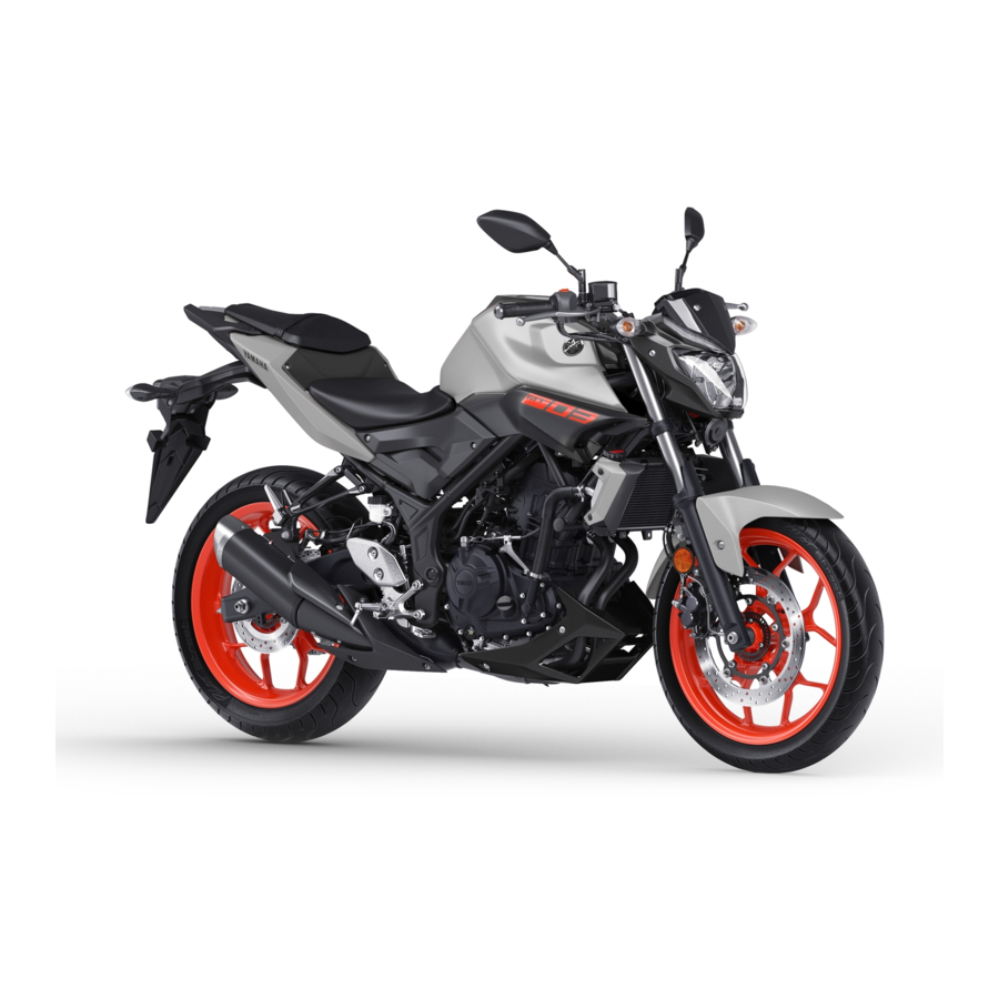
- Page 1 OWNER’S MANUAL MT-03 MOTORCYCLE Read this manual carefully before oper- ating this vehicle. MTN320-A B6W-F8199-E0...
- Page 2 EAU46094 Read this manual carefully before operating this vehicle. This manual should stay with this vehicle if it is sold.
- Page 3 Please take the time to read this manual thoroughly, so as to enjoy all advantages of your MTN320-A. The Owner’s Manual does not only instruct you in how to op- erate, inspect and maintain your motorcycle, but also in how to safeguard yourself and others from trouble and injury.
- Page 4 *Product and specifications are subject to change without notice. EAUN0430 MTN320-A OWNER’S MANUAL ©2020 PT Yamaha Indonesia Motor Manufacturing 1st edition, October 2019 All rights reserved. Any reprinting or unauthorized use without the written permission of...
-
Page 5: Table Of Contents
Table of contents Safety information ......1-1 Periodic maintenance charts ..6-3 Periodic maintenance chart for Description ........2-1 the emission control system..6-3 Left view ..........2-1 General maintenance and Right view........2-2 lubrication chart......6-4 Controls and instruments....2-3 Checking the spark plugs ....6-7 Canister........... - Page 6 Table of contents Replacing the license plate light bulb ........6-33 Supporting the motorcycle... 6-34 Troubleshooting......6-35 Troubleshooting chart ....6-36 Motorcycle care and storage..7-1 Matte color caution ......7-1 Care ..........7-1 Storage ........... 7-4 Specifications........8-1 Consumer information..... 9-1 Identification numbers....
-
Page 7: Safety Information
Safety information EAU1028C an accident or equipment damage. See page 4-1 for a list of pre-operation checks. Be a Responsible Owner This motorcycle is designed to As the vehicle’s owner, you are re- carry the operator and a passen- sponsible for the safe and proper oper- ger. - Page 8 Safety information Many accidents involve inexperi- • The passenger should always enced operators. In fact, many op- hold onto the operator, the seat erators who have been involved in strap or grab bar, if equipped, accidents do not even have a cur- with both hands and keep both rent motorcycle license.
- Page 9 Safety information Avoid Carbon Monoxide Poisoning extra care when riding a motorcycle All engine exhaust contains carbon that has added cargo or accessories. monoxide, a deadly gas. Breathing Here, along with the information about carbon monoxide can cause head- accessories below, are some general aches, dizziness, drowsiness, nausea, guidelines to follow if loading cargo to confusion, and eventually death.
- Page 10 Genuine before using it to make sure that it Yamaha accessories, which are avail- does not in any way reduce able only from a Yamaha dealer, have ground clearance or cornering been designed, tested, and approved clearance, limit suspension travel, by Yamaha for use on your vehicle.
- Page 11 Safety information operator and may limit control handlebars or turn signals, or ability, therefore, such accesso- parts that could break). Choose ries are not recommended. the location for the straps carefully Use caution when adding electri- so the straps will not rub against cal accessories.
-
Page 12: Description
Description EAU63371 Left view 3 4 5 1. Coolant reservoir (page 6-12) 2. Main fuse (page 6-31) 3. Tool kit (page 6-2) 4. Passenger seat lock (page 3-17) 5. Storage compartment (page 3-20) 6. Shock absorber assembly spring preload adjusting ring (page 3-20) 7. -
Page 13: Right View
Description EAU63391 Right view 10 9 1. Fuse box (page 6-31) 2. Battery (page 6-29) 3. Fuel tank cap (page 3-14) 4. Auxiliary light 5. Headlight (page 6-33) 6. Engine oil filler cap (page 6-8) 7. Engine oil level check window (page 6-8) 8. -
Page 14: Controls And Instruments
Description EAU63401 Controls and instruments 1. Clutch lever (page 3-11) 2. Left handlebar switches (page 3-10) 3. Multi-function meter unit (page 3-4) 4. Main switch/steering lock (page 3-1) 5. Front brake fluid reservoir (page 6-21) 6. Right handlebar switches (page 3-10) 7. -
Page 15: Instrument And Control Functions
Instrument and control functions EAU10462 EAU1068B Main switch/steering lock LOCK The steering is locked and all electrical systems are off. The key can be re- moved. To lock the steering LOCK The main switch/steering lock controls the ignition and lighting systems, and is used to lock the steering. -
Page 16: Indicator Lights And Warning Lights
Instrument and control functions From the “LOCK” position, push the EAU4939H Indicator lights and warning key in and turn it to “OFF”. lights 123 4 5 67 MPG mile 1. Engine trouble warning light “ ” 2. Oil pressure warning light “ ”... - Page 17 If the warning light remains on after adding oil, When the vehicle is turned on, this light stop the engine and have a Yamaha should come on for a few seconds and dealer check the vehicle. then go off. If the light does not come...
-
Page 18: Multi-Function Meter Unit
Instrument and control functions EAU87090 EAU86831 Multi-function meter unit Speedometer The speedometer shows the vehicle’s 8910 traveling speed. EAU87170 Tachometer MPG mile 1. “RESET” button 2. “SELECT” button 3. Clock 4. Coolant temperature meter MPG mile 5. Transmission gear display 1. - Page 19 If a problem is detected in the electrical circuit, the fuel level segments will flash MPG mile repeatedly. If this occurs, have a Yamaha dealer check the vehicle. 1. Coolant temperature meter EAU87290 Clock This meter shows the temperature of the coolant, and thereby the condition of the engine.
- Page 20 Instrument and control functions EAU87580 Multi-function display The odometer will lock at 999999 and cannot be reset. EAU88050 Tripmeters The tripmeters show the distance trav- eled since they were last reset. MPG mile To reset a tripmeter, change the dis- play to the tripmeter you want to reset, and then push the “RESET”...
- Page 21 Instrument and control functions EAU87680 EAU87771 Oil change tripmeter Instantaneous fuel consumption display 1. Oil change indicator “OIL” 2. Oil change tripmeter 1. Instantaneous fuel consumption display This tripmeter shows the distance trav- This display shows the fuel consump- eled since the last engine oil change. tion under the current riding condi- The oil change indicator “OIL”...
- Page 22 Instrument and control functions EAU87860 EAU87960 Average fuel consumption display Shift indicator light control mode 1. Shift indicator light “ ” 1. Average fuel consumption display 2. Brightness level display This display shows the average fuel This mode cycles through 4 control consumption since it was last reset.
- Page 23 Instrument and control functions setting is selected when the 1. Push the “RESET” button to select shift indicator light flashes 4 the desired engine speed for de- times per second. activating the shift indicator light. Off setting: the shift indicator 2.
-
Page 24: Handlebar Switches
Instrument and control functions EAU1234M EAU12461 Handlebar switches Turn signal switch “ ” To signal a right-hand turn, push this Left switch to “ ”. To signal a left-hand turn, push this switch to “ ”. When released, the switch returns to the cen- ter position. -
Page 25: Clutch Lever
Instrument and control functions ECA10062 EAU12823 Clutch lever NOTICE Do not use the hazard lights for an extended length of time with the en- gine not running, otherwise the bat- tery may discharge. 1. Clutch lever To disengage the drivetrain from the engine, such as when shifting gears, pull the clutch lever toward to the han- dlebar. -
Page 26: Shift Pedal
Instrument and control functions EAU12876 EAU12892 Shift pedal Brake lever 1. Shift pedal 1. Brake lever The shift pedal is located on the left The brake lever is located on the right side of the motorcycle. To shift the side of the handlebar. To apply the transmission to a higher gear, move front brake, pull the lever toward the the shift pedal up. -
Page 27: Brake Pedal
Instrument and control functions EAU12944 EAU63040 Brake pedal The Yamaha ABS (Anti-lock Brake System) features a dual electronic con- trol system, which acts on the front and rear brakes independently. Operate the brakes with ABS as you would conventional brakes. If the ABS... -
Page 28: Fuel Tank Cap
ABS is op- erating. However, special tools are required, so please consult your Yamaha dealer. ECA20100 NOTICE Be careful not to damage the wheel sensor or wheel sensor rotor; other- 1. -
Page 29: Fuel
Stop filling when the fuel EAU86071 reaches the bottom of the filler Your Yamaha engine was designed to tube. Because fuel expands when use unleaded gasoline with a research it heats up, heat from the engine or octane number of 90 or higher. -
Page 30: Fuel Tank Overflow Hose
10% (E10). Gas- ohol containing methanol recommended by Yamaha because it See page 6-8 for canister information. can cause damage to the fuel system or vehicle performance problems. ECA11401 NOTICE Use only unleaded gasoline. -
Page 31: Catalytic Converter
Instrument and control functions EAU13435 EAU62622 Catalytic converter Seats The exhaust system contains catalytic converter(s) to reduce harmful exhaust Passenger seat emissions. EWA10863 To remove the passenger seat WARNING 1. Insert the key into the seat lock, and then turn it clockwise. The exhaust system is hot after op- eration. - Page 32 Instrument and control functions Rider seat To remove the rider seat 1. Remove the passenger seat. 2. Remove the center cover by re- moving the screws. 1. Projection 2. Seat holder 2. Install the rider seat bolts. 3. Install the center cover by install- ing the screws.
-
Page 33: Helmet Holders
Instrument and control functions EAU62930 To release a helmet from a helmet Helmet holders holder Remove the passenger seat, remove the helmet from the helmet holder, and then install the seat. 1. Helmet holder The helmet holders are located on the bottom of the passenger seat. -
Page 34: Storage Compartment
Instrument and control functions EAU62550 EAU68143 Storage compartment Adjusting the shock absorber assembly This shock absorber assembly is equipped with a spring preload adjust- ing ring. ECA10102 NOTICE To avoid damaging the mechanism, do not attempt to turn beyond the maximum or minimum settings. -
Page 35: Luggage Strap Holders
Instrument and control functions EAU84680 Luggage strap holders 3 2 1 7 6 5 4 1. Extension bar 2. Special wrench 1. Luggage strap holder 3. Spring preload adjusting ring Use the indicated strap points to se- 4. Position indicator cure luggage ties to the vehicle. -
Page 36: Sidestand
Therefore, check this system regularly and have a Yamaha dealer repair it if it does not function properly. 3-22... - Page 37 5. Push the start switch. Does the engine start? The neutral switch may not be working. The motorcycle should not be ridden until checked by a Yamaha dealer. With the engine still running: 6. Move the sidestand up. 7. Pull the clutch lever.
-
Page 38: For Your Safety - Pre-Operation Checks
Do not operate the vehicle if you find any problem. If a problem cannot be corrected by the procedures provided in this manual, have the vehicle inspected by a Yamaha dealer. Before using this vehicle, check the following points:... - Page 39 • Tighten if necessary. Instruments, lights, • Check operation. — • Correct if necessary. signals and switches • Check operation of ignition circuit cut-off system. Sidestand switch • If system is not working correctly, have Yamaha dealer 3-22 check vehicle.
-
Page 40: Operation And Important Riding Points
0 and 1600 km (1000 mi). For understand, ask your Yamaha dealer. this reason, you should read the fol- EWA10272 lowing material carefully. -
Page 41: Starting The Engine
(6 mi/h). ECA24110 NOTICE If a warning or indicator light does not work as described above, have a Yamaha dealer check the vehicle. 3. Shift the transmission into the neutral position. 4. Start the engine by pushing the start switch. -
Page 42: Shifting
Operation and important riding points EAUM3632 EAU16674 Shifting This model is equipped with: a lean angle sensor. This sensor stops the engine in case of a vehi- cle turnover. If this happens, the engine trouble warning light will come on, but this is not a malfunc- tion. -
Page 43: Tips For Reducing Fuel Consumption
Operation and important riding points and drive train, which are not EAU16811 Tips for reducing fuel con- designed withstand sumption shock of forced shifting. Fuel consumption depends largely on your riding style. Consider the follow- ing tips to reduce fuel consumption: ... -
Page 44: Parking
Operation and important riding points EAU17214 Parking When parking, stop the engine, and then remove the key from the main switch. EWA10312 WARNING Since the engine and exhaust system can become very hot, park in a place where pedestri- ans or children are not likely to touch them and be burned. -
Page 45: Periodic Maintenance And Adjustment
If you are not familiar with vehicle ser- vice, have a Yamaha dealer perform service. EWA15123 WARNING Turn off the engine when performing... -
Page 46: Tool Kit
However, a torque wrench and other tools are necessary to perform certain maintenance work correctly. If you do not have the tools or experi- ence required for a particular job, have your Yamaha dealer perform it for you. -
Page 47: Periodic Maintenance Charts
Periodic maintenance and adjustment EAU71033 Periodic maintenance charts Items marked with an asterisk should be performed by your Yamaha dealer because these items require special tools, data, and technical skills. From 50000 km (30000 mi), repeat the maintenance intervals starting from 10000 km (6000 mi). -
Page 48: General Maintenance And Lubrication Chart
X 1000 km X 1000 mi • Perform dynamic inspection Diagnostic system √ √ √ √ √ √ using Yamaha diagnostic tool. check • Check the error codes. √ √ 2 * Air filter element • Replace. Air filter case √ √... - Page 49 Periodic maintenance and adjustment ODOMETER CHECK OR READINGS MAINTENANCE JOB ITEM X 1000 km X 1000 mi • Check bearing assemblies for √ √ √ looseness. 14 * Steering bearings • Moderately repack with lithium- √ √ soap-based grease. • Make sure that all nuts, bolts √...
- Page 50 Periodic maintenance and adjustment ODOMETER CHECK OR READINGS MAINTENANCE JOB ITEM X 1000 km X 1000 mi Moving parts and √ √ √ √ √ 28 * • Lubricate. cables • Check operation and free play. • Adjust the throttle cable free Throttle grip hous- √...
-
Page 51: Checking The Spark Plugs
The spark plugs are important engine components, which should checked periodically, preferably by a Yamaha dealer. Since heat and depos- its will cause any spark plug to slowly erode, they should be removed and checked in accordance with the peri- odic maintenance and lubrication 1. -
Page 52: Canister
Periodic maintenance and adjustment EAU36112 EAUN1150 Canister Engine oil and oil filter car- tridge The engine oil level should be checked before each ride. In addition, the oil must be changed and the oil filter car- tridge replaced at the intervals speci- fied in the periodic maintenance and lubrication chart. - Page 53 An oil filter wrench is available at a crankcase. Yamaha dealer. 7. Apply a thin coat of clean engine oil to the O-ring of the new oil filter cartridge.
- Page 54 Periodic maintenance and adjustment 1. O-ring 1. Engine oil drain bolt 2. Gasket Tightening torque: Make sure that the O-ring is properly Engine oil drain bolt: seated. 20 N·m (2.0 kgf·m, 15 lb·ft) 8. Install the new oil filter cartridge 10.
-
Page 55: Why Yamalube
1960’s helps make Yamalube the is correct, immediately turn the en- best choice for your Yamaha engine. gine off and have a Yamaha dealer check the vehicle. 13. Turn the engine off, wait a few minutes until the oil settles, and then check the oil level and cor- rect it if necessary. -
Page 56: Coolant
A slight tilt to the corrosion. If water has been side can result in a false reading. added to the coolant, have a Yamaha dealer check the anti- 2. Check the coolant level in the freeze content of the coolant as coolant reservoir. -
Page 57: Replacing The Air Filter Element And Cleaning The Check Hose
Changing the coolant The coolant must be changed at the in- tervals specified in the periodic mainte- nance and lubrication chart. Have a Yamaha dealer change the coolant. WARNING! Never attempt to remove the radiator cap when the engine is hot. - Page 58 Periodic maintenance and adjustment case. The engine should never be operated without the air filter element installed, otherwise the piston(s) and/or cylinder(s) may become excessively worn. [ECA10482] 7. Install the air filter case cover by installing the screws, and then place the rubber covers in their original positions.
-
Page 59: Checking The Throttle Grip Free Play
This service must be performed when 1. Throttle grip free play the engine is cold. Throttle grip free play: 3.0–5.0 mm (0.12–0.20 in) Periodically check the throttle grip free play and, if necessary, have a Yamaha dealer adjust it. 6-15... -
Page 60: Tires
The tires must be checked before each ride. If the center tread depth reaches the specified limit, if the tire has a nail or glass fragments in it, or if the side- wall is cracked, have a Yamaha dealer replace the tire immediately. 6-16... - Page 61 After extensive tests, only the tires list- ed below have been approved for this EWA10472 model by Yamaha. WARNING Have a Yamaha dealer replace Front tire: excessively worn tires. Besides Size: being illegal, operating the vehi- 110/70R-17M/C 54H...
-
Page 62: Cast Wheels
If any damage is found, have a Yamaha dealer replace the wheel. Do not attempt even the smallest repair to the wheel. A de- formed or cracked wheel must be replaced. -
Page 63: Checking The Brake Lever Free Play
There should be no free play at the adjusting nut in direction (a). To brake lever end. If there is free play, decrease the clutch lever free have a Yamaha dealer inspect the play, turn the adjusting nut in di- brake system. rection (b). -
Page 64: Brake Light Switches
To check the brake pad wear, check the wear indicator grooves. If a brake pad has worn to the point that the wear indicator grooves have almost disap- peared, have a Yamaha dealer replace the brake pads as a set. 6-20... -
Page 65: Checking The Brake Fluid Level
To check the brake pad wear, check the wear indicator grooves. If a brake pad has worn to the point that the wear indicator grooves have almost disap- peared, have a Yamaha dealer replace the brake pads as a set. 1. Minimum level mark Rear brake 1. -
Page 66: Changing The Brake Fluid
A low brake fluid level may indi- EAU22734 Changing the brake fluid cate worn brake pads or brake Have a Yamaha dealer change the system leakage; therefore, be sure brake fluid every 2 years. In addition, to check the brake pads for wear have the seals of the master cylinders and the brake system for leakage. -
Page 67: Drive Chain Slack
EAU22762 EAU62983 Drive chain slack To adjust the drive chain slack Consult a Yamaha dealer before ad- The drive chain slack should be justing the drive chain slack. checked before each ride and adjusted 1. Remove the drive chain puller cap, if necessary. -
Page 68: Cleaning And Lubricating The Drive Chain
Periodic maintenance and adjustment EAU23026 Cleaning and lubricating the Using the alignment marks on each drive chain side of the swingarm, make sure that The drive chain must be cleaned and both drive chain pullers are in the same lubricated at the intervals specified in position for proper wheel alignment. -
Page 69: Checking And Lubricating The Cables
Yamaha dealer at the intervals cated if necessary. If a cable is specified in the periodic maintenance damaged or does not move smoothly, chart. -
Page 70: Checking And Lubricating The Brake And Shift Pedals
Periodic maintenance and adjustment EAU44276 EAU23144 Checking and lubricating the Checking and lubricating the brake and shift pedals brake and clutch levers The operation of the brake and shift The operation of the brake and clutch pedals should be checked before each levers should be checked before each ride, and the pedal pivots should be lu- ride, and the lever pivots should be lu-... -
Page 71: Checking And Lubricating The Sidestand
The operation of the sidestand should The swingarm pivots must be lubricat- be checked before each ride, and the ed by a Yamaha dealer at the intervals sidestand pivot and metal-to-metal specified in the periodic maintenance contact surfaces should be lubricated and lubrication chart. -
Page 72: Checking The Front Fork
If any free over. play can be felt, have a Yamaha [EWA10752] 2. While applying the front brake, dealer check or repair the steer- push down hard on the handle- ing. -
Page 73: Checking The Wheel Bearings
It is a VRLA (valve-regulated lead- hub or if the wheel does not turn acid) battery. There is no need to check smoothly, have a Yamaha dealer the electrolyte or to add distilled water. check the wheel bearings. However, the battery lead connections need to be checked, and tightened if necessary. - Page 74 NOTICE Always keep the battery charged. To charge the battery Storing a discharged battery can Have your Yamaha dealer charge the cause permanent battery damage. battery if it seems to have discharged. Keep in mind that the battery tends to...
-
Page 75: Replacing The Fuses
Periodic maintenance and adjustment EAU62776 5. Connect the starter relay coupler, Replacing the fuses and then slide the cover to its orig- The main fuse is located under the inal position. passenger seat. The fuse box, which 6. Place the tray in its original posi- contains the fuses for the individual cir- tion, and then install the quick fas- cuits, is located behind the center pan-... - Page 76 4. If the fuse immediately blows 1. Spare fuse again, have a Yamaha dealer 2. ABS solenoid fuse 3. ABS motor fuse check the electrical system. If a fuse is blown, replace it as follows.
-
Page 77: Vehicle Lights
2. Remove the rear fender lower check the fuses and then have a panel by removing the bolts and Yamaha dealer check the vehicle. If the screws. license plate light does not come on, check and replace the bulb. (See page 6-33.) -
Page 78: Supporting The Motorcycle
Periodic maintenance and adjustment EAU24351 Supporting the motorcycle Since this model is not equipped with a centerstand, follow these precautions when removing the front and rear wheel or performing other mainte- nance requiring the motorcycle to stand upright. Check that the motorcy- cle is in a stable and level position be- fore starting any maintenance. -
Page 79: Troubleshooting
The following troubleshooting charts represent quick and easy procedures for checking these vital systems your- self. However, should your motorcycle require any repair, take it to a Yamaha dealer, whose skilled technicians have the necessary tools, experience, and know-how to service the motorcycle properly. -
Page 80: Troubleshooting Chart
Check the vehicle. compression. 4. Compression The engine does not start. There is compression. Have a Yamaha dealer check the vehicle. Try starting the engine. There is no Have a Yamaha dealer check the vehicle. compression. 6-36... - Page 81 Start the engine. If the engine overheats again, The coolant level is have a Yamaha dealer check and repair the cooling system. If coolant is not available, tap water can be temporarily used instead, provided that it is changed to the recommended coolant as soon as possible.
-
Page 82: Motorcycle Care And Storage
Be of many components. Washing, clean- sure to consult a Yamaha dealer for ing, and polishing will also give you a advice on what products to use be- chance to inspect the condition of the fore cleaning the vehicle. - Page 83 Motorcycle care and storage harsh chemicals, including Washing strong acidic wheel cleaners, 1. Rinse off any degreaser and spray especially on spoke or magne- down the vehicle with a garden sium wheels. hose. Use only enough pressure harsh to do the job.
- Page 84 Motorcycle care and storage 2. For drive chain-equipped models: ECA26320 NOTICE Dry and then lubricate the drive Do not apply wax to rubber or chain to prevent rust. 3. Use a chrome polish to shine unpainted plastic parts. Do not use abrasive polishing chrome, aluminum, and stainless steel parts.
-
Page 85: Storage
Motorcycle care and storage EAU83472 5. For vehicles with a carburetor: To Storage prevent fuel deposits from build- Always store the vehicle in a cool, dry ing up, drain the fuel in the carbu- place. If necessary, protect it against retor float chamber into a clean dust with a porous cover. - Page 86 Motorcycle care and storage 8. Check and correct the tire air pressure, and then lift the vehicle so that all wheels are off the ground. Otherwise, turn wheels a little once a month in or- der to prevent the tires from be- coming degraded in one spot.
-
Page 87: Specifications
Specifications *Dimensions: With oil filter removal: 2.10 L (2.22 US qt, 1.85 Imp.qt) Overall length: *Coolant quantity: 2090 mm (82.3 in) Overall width: Coolant reservoir (up to the maximum level 755 mm (29.7 in) mark): Overall height: 0.25 L (0.26 US qt, 0.22 Imp.qt) 1070 mm (42.1 in) Radiator (including all routes): Seat height:... - Page 88 Specifications *Loading: Maximum load: 160 kg (353 lb) (Total weight of rider, passenger, cargo and accessories) *Front brake: Type: Hydraulic single disc brake *Rear brake: Type: Hydraulic single disc brake *Front suspension: Type: Telescopic fork *Rear suspension: Type: Swingarm *Electrical system: System voltage: 12 V *Battery:...
-
Page 89: Consumer Information
Record the vehicle identification num- ber and the engine serial number in the spaces provided below for assistance when ordering spare parts from a Yamaha dealer or for reference in case the vehicle is stolen. VEHICLE IDENTIFICATION NUMBER: 1. Engine serial number The engine serial number is stamped into the crankcase. -
Page 90: Diagnostic Connector
Privacy Policy. Privacy Policy https://www.yamaha-motor.eu/eu/ privacy/privacy-policy.aspx Yamaha will not disclose this data to a third party except in the following cas- es. In addition, Yamaha may provide vehicle data to a contractor in order to outsource services related to the han- dling of vehicle data. -
Page 91: Index
Index ABS ............3-13 Handlebar switches ......3-10 ABS warning light........3-3 Hazard switch ........3-10 Air filter element and check hose, Helmet holders........3-19 replacing and cleaning....... 6-13 High beam indicator light......3-2 Horn switch........... 3-10 Battery..........6-29 Brake and clutch levers, Identification numbers ...... - Page 92 Index Tachometer..........3-4 Throttle grip and cable, checking and lubricating ....6-25 Throttle grip free play, checking ...6-15 Tires ............6-16 Tool kit ............6-2 Transmission gear display ......3-5 Troubleshooting........6-35 Troubleshooting chart......6-36 Turn signal indicator lights......3-2 Turn signal switch .........3-10 Valve clearance........6-15 Vehicle identification number ....9-1 Vehicle lights.........6-33 Wheel bearings, checking.....6-29 Wheels ..........6-18...
- Page 94 PRINTED IN INDONESIA 2019.10...
Need help?
Do you have a question about the MTN320-A and is the answer not in the manual?
Questions and answers