Table of Contents
Advertisement
Quick Links
Advertisement
Table of Contents

Subscribe to Our Youtube Channel
Related Manuals for DEI PCX-7420 B


Summary of Contents for DEI PCX-7420 B
- Page 1 PCX-7420 B Pulsed Current Source Operation Manual Directed Energy, Inc. 1609 Oakridge Dr., Suite 100, Fort Collins, CO 80525 (970) 493-1901 sales@directedenergy.com www.directedenergy.com Document #7650-0037, Rev. A2 © Copyright 2019, Directed Energy, Inc. All rights reserved.
-
Page 3: Table Of Contents
Set the Trigger Type ..................13 Set the Termination ..................14 Set the Frequency ..................15 View Information About the PCX-7420 B ........... 15 Save Settings ....................16 Recall Settings .................... 16 Warnings and Faults ..................17 ... -
Page 4: Safety
• Do not open the cover of PCX-7420 B. There are no user-serviceable parts inside. Opening the cover exposes you to lethal shock and voids the factory warranty. -
Page 5: Introduction
OLED screen or by computer control via RS-232 or USB interface. The bias feature allows the PCX-7420 B to deliver a current pulse in two steps. The first step—the bias pulse—starts before the intended trigger time. Current is set just below the lasing point, minimizing the diode’s response time to the main... -
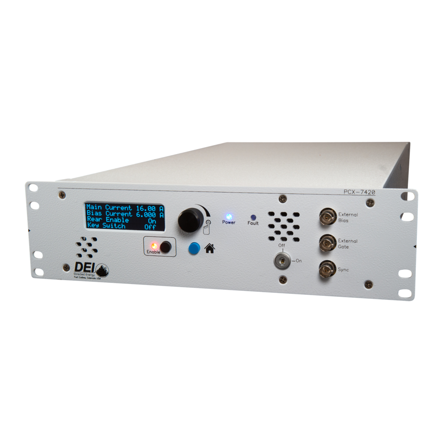
Page 6: Panel Layout
Panel Layout All features of the front and rear panel are labeled. Their functions are covered in the next section. Page 6 of 28 For more information: 970.493.1901 or sales@directedenergy.com Document #7650-0037 Rev A2. © Copyright 2019 Directed Energy, Inc. All rights reserved. -
Page 7: Front Panel Features
(increments of value change). When finished changing the parameter, press HOME to exit the parameter screen. Keyswitch Allows the PCX-7420 B to be enabled when ON. Disables the PCX-7420 B and prevents the system from being enabled when OFF. External Bias Input Accepts bias trigger pulses from an external source via a BNC connector. -
Page 8: Rear Panel Features
Rear Panel Features Output Accepts the factory-supplied output cable and provides the generated current pulses. DO NOT TOUCH any part of this cable while the PCX-7420 B is powered up. Please review the Safety section above. Rear Enable Accepts either an external dry-contact closure or the factory-supplied shorting BNC plug. -
Page 9: Accessories Included
Accessories Included AC Power Cable Factory-supplied standard computer-style power cord with NEMA C14 and NEMA 5- 15R connectors. Shorting BNC Plug Attaches to the Rear Enable BNC connector. Enables the output when a closed- contact system is not used. Keyswitch Keys Keys for the front-panel keyswitch that allows the output to be enabled. - Page 10 Laser Output PCBA A factory-supplied laser output circuit board that provide a simple method to interface a laser or other external device. Page 10 of 28 For more information: 970.493.1901 or sales@directedenergy.com Document #7650-0037 Rev A2. © Copyright 2019 Directed Energy, Inc. All rights reserved.
-
Page 11: Operation
Operation Setup 1. Make sure the PCX-7420 B has been OFF for at least ten minutes. 2. Make sure the polarity of the diode connection is correct. If necessary, review the output cable pinout in the Specifications section. 3. Connect the output cable from the PCX-7420 B to the output device. -
Page 12: Set The Bias Output Current
3. Rotate the encoder knob to change the value. The range is 3 A to 15.7 A. 4. Press the encoder knob to change the multiplier to x0.001, x0.010, x0.100, x1.000, or x10.000 indicated by the Main Current asterisk (*). ------------ 5. -
Page 13: Set The Bias Width
Pulse width resolution, internal 40 Hz to 300 Hz: 6400 ns 300 Hz to 5000 Hz: 1600 ns 5 kHz to 100 kHz: 100 ns For external settings: 1. Set the Pulse Width on the external signal generator. Set the Bias Width Bias Pulsewidth TRIG:INT:BIAS:PULSEWIDTH? ---------------... -
Page 14: Set The Termination
Gate information. It is recommended to Trigger Type disable the system prior to switching ------------ between internal external Internal triggering. Press KNOB to update 1. Rotate the encoder knob to the Trigger Type screen. 2. Press the encoder knob to select the Trigger Type Trigger Type. -
Page 15: Set The Frequency
5 kHz to 100 kHz: 1000 Hz For external settings: 1. Set the Frequency on the external signal generator. View Information About the PCX-7420 B *IDN? 1. On the Home screen, rotate the PCX-7420 B encoder knob counter-clockwise 1 -------- screen. -
Page 16: Save Settings
Save Settings *SAVE n 1. Rotate the encoder knob to the Save Save Settings Settings screen. ------------- 2. Press the encoder knob to enter the save menu. 3. Rotate the encoder knob to choose a Press KNOB to save memory location from 1 to 5. -
Page 17: Warnings And Faults
Warnings and Faults All faults disable the PCX-7420 B. To continue after clearing a fault, you must send an “OUTPUT:ENABLE” command from the computer or press the ENABLE button on the front panel. Keyswitch Status STATUS:KEYSWITCH? ******************** The keyswitch was OFF at power-... -
Page 18: View The Communication Settings
4. If the USB port is connected to a computer, RS-232 is disabled automatically. 5. The USB driver can be found at https://directedenergy.com 6. During computer communication to the PCX-7420 B, the screen will change and report the Baud rate, the number of data bits and stop bits, and the parity. ... -
Page 19: Command Set
Commands and queries that require data, denoted as n, must have a space between the command and the data. For every command sent to the PCX-7420 B, a response will be sent back to the user from the PCX-7420 B. The user’s software must wait for a response before sending another command to avoid an overflow of the PCX-7420 B receive buffer. - Page 20 The commands are in alphabetical order except *LIST?. In the examples, the command or query is in black; the response is in blue italics. *LIST? Lists all commands and queries supported by the PCX-7420 B. Example: *LIST? *IDN? *SAVE *RECALL...
- Page 21 *IDN? Short for Identity; returns the manufacturer’s name, unit model number, serial number, firmware revisions, and manufacture date. Example: *IDN? DEI Scientific, PCX-7420 B, 110-081, D03 M04, 00 MAIN:CURRENT:SETPOINT? Returns the setpoint of main current in mA. Example: MAIN:CURRENT:SETPOINT? 15000 mAmps MAIN:CURRENT:SETPOINT n Sets the amount of main current in mA.
- Page 22 OUTPUT:ENABLE (if successful) If a fault is preventing the PCX-7420 B from enabling, clear the fault by pressing the HOME button. If the keyswitch is not ON or the rear enable connection is not made fix the system by turning on the keyswitch or connecting the rear enable BNC.
- Page 23 TEMP:IN? Returns the temperature of the intake air in degrees Celsius. Example: TEMP:IN? 27 °C TEMP:EXHAUST? Returns the temperature of the exhaust air in degrees Celsius. Example: TEMP:EXHAUST? 38 °C TRIG? Returns the whether the trigger is internal or external. Example: TRIG? INTERNAL TRIG:EXTERNAL...
- Page 24 TRIG:INT:FREQ? Returns the internal trigger frequency in hertz. Example: TRIG:INT:FREQ? 2400 Hz TRIG:INT:FREQ n Sets the internal trigger frequency in hertz. The value of n must be from 40 to 100000. Example: TRIG:INT:FREQ 2400 TRIG:INT:FREQ 2400 TRIG:INT:MAIN:PULSEWIDTH? Returns the pulse width of the main current pulse, in nanoseconds. Example: TRIG:INT:MAIN:PULSEWIDTH? 280000 nsec...
-
Page 25: Warranty And Service
Connected, installed, adjusted, or used otherwise than in accordance with instructions furnished by DEI. DEI reserves the right to make any changes in the design or construction of its products at any time, without incurring any obligation to make any change whatever in units previously delivered. -
Page 26: Ce Declaration
CE Declaration Page 26 of 28 For more information: 970.493.1901 or sales@directedenergy.com Document #7650-0037 Rev A2. © Copyright 2019 Directed Energy, Inc. All rights reserved.
Need help?
Do you have a question about the PCX-7420 B and is the answer not in the manual?
Questions and answers