
Subscribe to Our Youtube Channel
Related Manuals for InoTec inoCOMB Picco Power


Summary of Contents for InoTec inoCOMB Picco Power
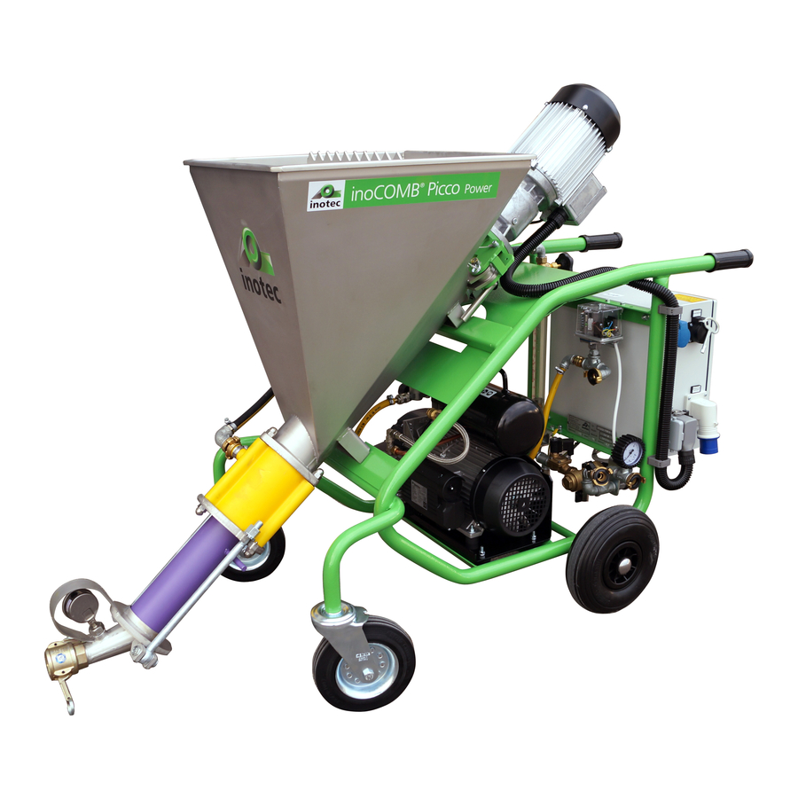
- Page 1 Operating Manual inoCOMB Picco Power mixing pump Read this entire original operating manual before starting work.
- Page 2 Thank you for trusting INOTEC. By purchasing you have opted for a quality product. If you have any suggestions or any issues, we would be delighted to hear your suggestions for improvement and your feedback. Speak to the sales representative assigned to you or, in urgent cases, contact us directly.
-
Page 3: Table Of Contents
3.9 Operating conditions ............................10 4 Assembly and function ........................... 10 4.1 Scope of delivery of inoCOMB Picco basic module ..................10 4.2 Scope of delivery of inoCOMB Picco Power set ....................10 4.3 Functionality ..............................10 4.4 Components ..............................11 4.4.1 Description of the components ............................11 4.4.1.1 Frame with material hopper, mixing pipe incl. - Page 4 12.3 Disposal ................................38 13 Systems ..............................39 13.1 EC declaration of conformity ........................39 13.2 General Terms of Business of the company INOTEC GmbH ................40 13.3 Circuit diagram for compressor ........................41 13.3.1 Circuit diagram for mixer motor safety switch ......................42 13.3.2 Circuit diagram for water pressure switch / air pressure switch ...................43 13.3.3 Circuit diagram for pump rotation speed ........................44...
-
Page 5: General Information
In the event of a warranty claim, send the entire machine, along with the invoice, to our headquarters in Waldshut- NOTE NOTICE draws your attention to useful tips for Tiengen. Contact our free INOTEC service hotline before- effectively handling the machine. hand on +49 7741 6805 777. Page 5... -
Page 6: Warranty Claims
Picco Power or other assets. WARNING Danger due to misuse! Misuse of the inoCOMB Picco Power may lead to dan- gerous situations. • Never use the inoCOMB Picco Power mixing pump to create other products, such as food. -
Page 7: Notices In The Operating Manual
• Do not make any changes, additions or conver- sions to the machine without first consulting Inotec GmbH and obtaining its written approval. Other- wise, the operating license will become void. Page 7... -
Page 8: Cleaning And Maintaining The Machine
4. After cleaning, remove all the covers which were at- tached to protect against the water. 2.2.5 Changing the location of the machine The inoCOMB Picco Power is equipped with four wheels. The inoBEAM can, therefore, be moved on the construction site conveniently. -
Page 9: Responsibility Of The Operator
2.5 Responsibility of the operator • Only task trained or instructed staff with operating the 3.1 Rating plate inoCOMB Picco Power. • Define employees’ responsibilities for operating, setting up, maintaining and servicing the machine clearly. • Only task untrained staff or individuals who have not re-... -
Page 10: Water Measuring System
= 50 Hz , I = 11.2 A, • Operating manual U = 230 V, IP 54 Insulation class F, ED = S1 4.2 Scope of delivery of inoCOMB Picco Power set (Item no. 10041149) Colour unvarnished As with the basic module (item no. 10041148) Plus: 3.6 Mixing coil... -
Page 11: Components
2.5 mm ! The inoMIX inoCOMB Picco Power may only be run with an approved FI circuit breaker (30 mA) (RCD), e.g. with the INOTEC PRCD-S personal protection switch (item no. 10015278). -
Page 12: Displays And Controls
Chapter 4 Assembly and function 4.5 Displays and controls 4.5.1 Switching cabinet NOTE Working with and without electric re- mote control. • When the remote control cable is plugged into the switching cabinet, the machine is switched on and off via the green push button at the end of the remote control cable. -
Page 13: Mixing Coil
Chapter 4 Assembly and function 4.5.2 Mixing coil 4.5.4 Water fitting The mixing coil is connected to the motor via the drive shaft and rotates during operation in the material hopper. The mixing coil is also connected to the rotor via a plug-in con- nection. -
Page 14: Air Fitting
Chapter 4 Assembly and function 4.6 Connections 4.6.1 Power connections (230 V) WARNING Water jet. Risk of injury and risk of property damage due to es- caping water. 1. Interrupt the external water supply by closing the water valve. 2. In order to release the pressure (approx. 2 bar), open the water drainage valve on the water measuring sys- tem under the pressure reducer. -
Page 15: Remote Control Connection
(switch position on the right). Connection of the electric remote control cable (2). 4.7 Operating modes The inoCOMB Picco Power can be fed with powdery ma- terial from bags, one-way containers (with the dry convey- ing unit inoFLEX Mono), big bags (with the Big-Bag-Box Mono), silos (with a conveyor system) or paste-like material from e.g. -
Page 16: Accessories
Chapter 4 Assembly and function 4.8 Accessories The following accessories can be supplied for the inoCOMB Picco Power. Ø Length Item no. Water/air hose • For universal use, e.g. air, water 1/2” 10 m 10022000 • GEKA couplings crimped with sleeves on both sides 1/2”... - Page 17 Chapter 4 Assembly and function Ø Length Item no. Plastic starting hose connector with V Part 35 35 mm 0.3 m 10038433 Hose holder Item no. • For rapidly fixing hoses to the scaffold 10018503 inoCOLL one-handed gun Item no. •...
- Page 18 Chapter 4 Assembly and function Jet nozzle Ø Item no. • For MAI finishing coat device 10 mm 10024378 12 mm 10024379 10024380 14 mm 16 mm 10024381 Straight finishing coat device Item no. • With 25 mm M-piece coupling 10024098 •...
- Page 19 • Standard mixing coil, for inoCOMB Picco Power 10017950 • Light material mixing coil, for inoCOMB Picco Power 10042441 • Mixing coil for materials that are difficult to evacuate for inoCOMB Picco Power 10036255 Rotor D4-½ output Item no. • Head marked in green 10022543 Rotor D4-½...
- Page 20 Scope of delivery: Frame with material hopper, vibrating unit (2 pieces), 230 V double adapter for vibrating units, threaded connector for inoFLEX Mono, Connection for industrial vacuum cleaner InoFLEX Mono dry conveying unit for inoCOMB Picco Power mixing pump Item no. The flexible inoFLEX Mono delivery shaft transports the material 10041947 to be processed from the Big-Bag-Box Mono directly into the mixing pump hopper.
-
Page 21: Spare Parts And Diagrams
Chapter 4 Assembly and function 4.9 Spare parts and diagrams The spare parts for the inoBEAM inoCOMB Picco Power are designated with numbers in the following images. The indi- vidual items are described in the table under the respective NOTE diagrams. - Page 22 Chapter 4 Assembly and function Item Item no. Installation Name quantity 10006192 Units Starlock cap 10042609 Units Rubber wheel, puncture-free 10042506 Units Stator D7-2.5 “Mono Plus”, maintenance-free 10022556 Units Rotor D7-2.5 “S”/Plus 10036281 Units Pressure flange D-pump 10022062 Units M-piece coupling 35, 1 1/4” IT 10015684 1.10 Meter Black cable protective hose...
-
Page 23: Water Measuring System Spare Parts List (Item No. 10041182)
Chapter 4 Assembly and function 4.9.2 Water measuring system spare parts list (item no. 10041182) 9 21 Item Item no. Installation Name quantity 10021968 0.97 Meter Rubber water hose, 1/2” 10022454 Units Hose clamp, 1/2” 10022372 Units GEKA coupling, 1/2” IT 10006497 Units Angular, 1/2”... -
Page 24: Air Fitting (Item No. 10041222)
Angular, 3/8” 90°, galvanised IT 10022201 Units Ewo quick-release coupling, V-piece, 3/8”, ET 10022372 Units GEKA coupling, 1/2” IT 10022156 Units Galvanised bend, DN 15, 1/2”, IT/ET 10041732 Units Holder for inoCOMB Picco Power air fitting 10022456 Units Hose clamp, 1/4” Page 24... -
Page 25: Drive Unit (Item No. 10043189)
Chapter 5 Transport and storage 4.9.4 Drive unit (item no. 10043189) 8 9 10 6 13 11 12 Motor Item Item no. Installation Name quantity 10043189 Units Spur gear motor, 3 kW with taper roller bearing, incl. motor flange 10016171 Units Complete safety switch 10034395... -
Page 26: Transport And Storage
2. Have the transport damage confirmed by means of the driver’s signature. 3. Send copy damage report transport company another Inotec GmbH. 4. And clarify the possible ways in which the damage could be remedied with one of our service centres (see second last page) Page 26... -
Page 27: Installation
• Install the inoCOMB Picco Power on an even and hori- zontal surface. • Prevent the machine from sliding by locking the front wheels. The mixing zone points downwards. -
Page 28: Installing The Mixing Coil
6.5 Connecting the electrical control system zone and place it in a bucket. 1. Connect the inoCOMB Picco Power only to regulation 8. Acknowledge the red flashing fault display by press- 230 V construction site power distribution points with FI ing the “Fault”... -
Page 29: Starting The Machine
Chapter 6 Installation 6.7 Starting the machine 1. Open both cam levers of the mortar coupling at the pump outlet (directly after the mortar pressure gauge). 2. Insert the male part of the starting hose (optional) into the mortar coupling and close both cam levers. 10. -
Page 30: Commissioning
Chapter 7 Commissioning 7 Commissioning 7.1 Adding material to the material hopper Warning Risk to health due to dust. When cleaning the machine, inhaled dust can cause long-term lung damage or other adverse health ef- 15. Turn the start switch to “0”. The machine will stop. fects. -
Page 31: Changing Material
Chapter 8 Operation, use 8 Operation, use 7.3 Changing material 1. Run the material hopper of the inoCOMB Picco Power until it is empty. 8.1 Checking operating performance 2. Then switch off the mixing pump and compressor. 1. If you notice any deviations in the operating behaviour, 3. -
Page 32: Areas Of Application
Chapter 9 Areas of application 9 Areas of application inoCOMB Picco Power Fine acoustic finishing coats Multi-layer acoustic spray plasters Concrete bonder Floor filling compounds Fire protection mortar Decorative fine coats Floating screeds Liquid woodchip Porous concrete coats Lime-based finishing plasters Lime plasters Lime cement plasters Machine-applied gypsum plasters... -
Page 33: Cleaning & Decommissioning
Chapter 10 Cleaning & decommissioning 10 Cleaning & decommissioning 10.1 Cleaning process 1. Stop filling with bagged goods in sufficient time. DANGER Rotating mixing shafts. 2. Close the air valve on the spray head. Turn the starter Danger of death due to being pulled into the machine switch to “0”. -
Page 34: After Cleaning
shop. Replace parts which are subject to wear as soon as the wear limits have been reached. Portable machines, like the inoCOMB Picco Power, must be subject to an annual elec- trical inspection according to the implementing regulation NOTE Note the optimum assembly sequence. -
Page 35: Dirt Trap Sieve In The Water Inlet
However, should a fault occur, please follow the instructions below on analysing, checking and remedying the fault or contact the Inotec Service team (see the address list for INOTEC service centres at the end of the document) or call the INOTEC service hotline on: +49 7741 6805 777. - Page 36 Chapter 11 Maintenance Symptom Potential cause Check / solution Personnel qualification If the machine will not Power supply is • Check the power supply (power distribution points, socket, Machine start. cut off. power cable, cable reel). operator No input voltage •...
- Page 37 Chapter 11 Maintenance Symptom Potential cause Check / solution Personnel qualification Pump is not Pump worn or delivery • Replace the pump. Machine delivering enough pressure too high. • If the delivery pressure is too high, reduce the hose length. operator material Pump is delivering no...
-
Page 38: Dismantling And Disposal
Risk of injury posed by improper disas- • Send the metal to a recycling facility. sembly. • Dispose of the inoCOMB Picco Power via a scrap metal Stored residual energy, sharp components, points and dealer or your local scrap metal collection centre. -
Page 39: Systems
EC Directive 2006/42/EC. This declaration will become void in the event of any modification made to the machine without our approval. Name of the device: inoCOMB Picco Power Machine model: Mixing pump... -
Page 40: General Terms Of Business Of The Company Inotec Gmbh
Allgemeinen genommen werden, wenn die Ansprüche gegen unsere Vorlieferanten trotz Geschäftsbedingungen zugrunde. IV. Gerät der Kunde mit der Zahlung in Verzug, kann die INOTEC GmbH rechtzeitiger (gerichtlicher) Inanspruchnahme nicht durchsetzbar sind bzw. die Abweichende oder in unseren Geschäftsbedingungen nicht enthaltene zumindest die gesetzlichen Verzugszinsen fordern. -
Page 41: Circuit Diagram For Compressor
Chapter 13 Systems 13.3 Circuit diagram for compressor Page 41... -
Page 42: Circuit Diagram For Mixer Motor Safety Switch
Chapter 13 Systems 13.3.1 Circuit diagram for mixer motor safety switch Page 42... -
Page 43: Circuit Diagram For Water Pressure Switch / Air Pressure Switch
Chapter 13 Systems 13.3.2 Circuit diagram for water pressure switch / air pressure switch Page 43... -
Page 44: Circuit Diagram For Pump Rotation Speed
Chapter 13 Systems 13.3.3 Circuit diagram for pump rotation speed Page 44... -
Page 45: Switching Cabinet Subplate, Inside
Chapter 13 Systems 13.3.4 Switching cabinet subplate, inside Page 45... -
Page 46: Switching Cabinet, Outside
Chapter 13 Systems 13.3.5 Switching cabinet, outside Page 46... -
Page 47: Order Form
Chapter 14 Order form 14 Order form Fax to: +49(0)7741-6805-665 Delivery address Invoice to Name of customer Consultant Date Number Item no. Item name Our General Terms of Business, Delivery and Payment apply. The customer has been made aware of these terms and agrees to the application of the same. -
Page 48: Index
Dismantling and disposal ..........38 Safety ................6 Displays and controls .............12 Scope of delivery of inoCOMB Picco basic module ..10 Scope of delivery of inoCOMB Picco Power set ....10 Spare parts and diagrams ..........21 EC declaration of conformity ..........39 Starting the machine ............29 Electrical control system, mixing rate, weight, dimensions 9 Storage ................26... -
Page 49: Locations
Chapter 16 Locations 16 Locations Your sales partner (English language) INOTEC GmbH (Headquarter) Daimlerstraße 9-11 79761 Waldshut-Tiengen Germany Phone +49 7741 / 6805 675 +49 7741 / 6805 665 E-Mail: j.tetling@inotec-gmbh.com Wherever you are, we’re there, too. Page 49... - Page 50 Accessories & Waste water Tillage Compressed air / air dehumidifiers spare parts systems compressors / high-pressure cleaners Power tools / electrical appliances INOTEC GmbH • Daimlerstraße 9-11 • D-79761 Waldshut-Tiengen • Tel.: +49 77 41 / 68 05-0 • www.inotec-gmbh.com...
Need help?
Do you have a question about the inoCOMB Picco Power and is the answer not in the manual?
Questions and answers