
Related Manuals for Electrolux Beef Eater 1600 Series


Summary of Contents for Electrolux Beef Eater 1600 Series
- Page 1 1600 SERIES Assembly and Operating Instructions TROLLEY MODELS BMG1641SA, BMG1651SA, BMG1641DA & BMG1651DA AUSTRALIA / NEW ZEALAND FOR OUTDOOR USE ONLY...
-
Page 2: Table Of Contents
CONGRATULATIONS CONTENTS Dear Customer, Important safety instructions ..........3 Product description ..............4 Congratulations and thank you for choosing our barbecue. Product dimensions ..............5 We are sure you will find it a pleasure to use. Before you use the barbecue, we recommend that you read through Assembling the barbecue ............ -
Page 3: Important Safety Instructions
IMPORTANT SAFETY INSTRUCTIONS • Do not attempt to dismantle or adjust the regulator. Please read the user manuals carefully and store in a handy place for later reference. • Do not test for leaks with a naked flame. • Do not modify the construction of this appliance or modify the injector orifice size. -
Page 4: Product Description
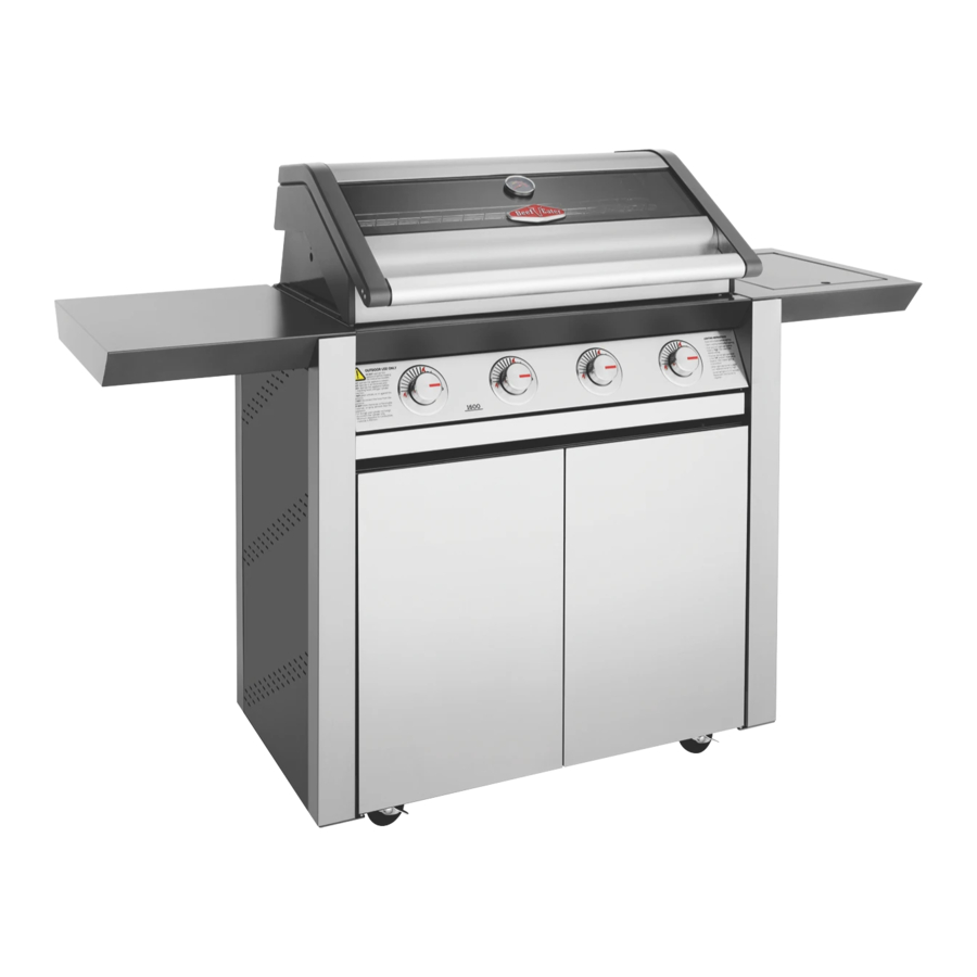
PRODUCT DESCRIPTION 4 burner barbecue Brace Side panel RH BMG1641 shown Door LH Door RH Left hand side table Base panel Locking castors x 2 Separation panel Right hand side burner Castors x 2 Side panel LH Rear panel Side panel support LH and RH PRODUCT DESCRIPTION... -
Page 5: Product Dimensions
PRODUCT DIMENSIONS 1670mm 804.5mm 686mm 610mm 1840mm 975mm Hood open DIMENSIONS... -
Page 6: Assembling The Barbecue
ASSEMBLING THE BARBECUE Tools required: Fasteners supplied: M6 x 10mm M5 x 10mm M4 x 10mm 12 Fibre 1 x Oval 1 x Circle 12 off 4 off (5 burner washers grommet grommet models only) Important: ensure locking casters are fitted to the front of the trolley, with locks facing forward. - Page 7 4 x screws for LHS panel Repeat same assembly 4 x screws for process on right hand M5 x 10mm RHS panel side panel. Fit screws but do no tighten to position subsequent M6 x 10mm screws more easily. ASSEMBLING THE BARBECUE...
- Page 8 ASSEMBLING THE BARBECUE Fit screws but do no tighten M6 x 10mm to position subsequent screws more easily. Fit screws but do no tighten to position subsequent M6 x 10mm screws more easily. ASSEMBLING THE BARBECUE...
- Page 9 Repeat same assembly process on right hand hinge plate. 2 x screws for LHS panel 2 x screws for M5 x 10mm RHS panel Tighten all screws to secure M6 x 10mm all panels. ASSEMBLING THE BARBECUE...
- Page 10 ASSEMBLING THE BARBECUE ASSEMBLING THE BARBECUE...
- Page 11 5 Burner model only M4 x 10mm M6 x 10mm ASSEMBLING THE BARBECUE...
- Page 12 ASSEMBLING THE BARBECUE First fit lower door pin into the hole on the base assembly. Then depress the upper door pin with your finger, line up with the hole above on the separator panel, and release to allow the pin into the hole. Remove the grease tray, then carefully lift the barbecue onto the trolley with two people, inserting the gas connector...
- Page 13 Repeat same assembly process on right hand side. M6 x 10mm Repeat same assembly process on right hand side. Refit the grease tray that was removed in step 14. M6 x 10mm ASSEMBLING THE BARBECUE...
- Page 14 ASSEMBLING THE BARBECUE Repeat same assembly process on right hand side. M6 x 10mm 4 x screws for LHS panel 4 x screws for RHS panel ASSEMBLING THE BARBECUE...
- Page 15 Install the flame tamers above the burners that will be under a grill plate. See below for configuration. For 4 burner models: For 5 burner models (to suit Option 1 plate and grill setup, see Step 20): For 5 burner models (to suit Option 2 plate and grill setup, see Step 20): ASSEMBLING THE BARBECUE...
- Page 16 ASSEMBLING THE BARBECUE Install the solid plate and grill/s in one of the below configuration options, in order to keep the fat drainage hole from being placed directly above a burner. For easier installation, place the solid plate first, followed by the grill plates.
- Page 17 For 5 burner models: Option 1 For 5 burner models: Option 2 ASSEMBLING THE BARBECUE...
- Page 18 ASSEMBLING THE BARBECUE Plate and grill removal The plate and grill may be removed for cleaning following below steps: First lift up the grill from the centre edge as pictured, then remove the solid plate (and 2nd grill if fitted) for cleaning. ASSEMBLING THE BARBECUE...
- Page 19 Connecting the side burner To connect the side burner: Disconnect the gas hose and regulator assembly (A) from the barbecue using 2 spanners. Connect the gas hose and regulator assembly (A) to the side burner connection using 2 spanners. ASSEMBLING THE BARBECUE...
- Page 20 ASSEMBLING THE BARBECUE Connect the gas hose (B) to the remaining connection on the side burner using 2 spanners. Connect the other side of gas hose (B) to the barbecue connection using 2 spanners ASSEMBLING THE BARBECUE...
- Page 21 IMPORTANT WARNING After completing the gas hose connections, conduct a leak test following the leak test procedure before using the appliance. WARNING WARNING To ensure gas tight connections, complete the gas leak test procedure before and after gas hose connection and after every reconnection of the gas cylinder.
-
Page 22: Side Burner Operating Instructions
SIDE BURNER OPERATING INSTRUCTIONS Control functions Manual lighting • In the event of the automatic ignition system not Before lighting the side burner: working, the barbecue can be lit manually • Check that all hoses and gas fittings are tight •... -
Page 23: Gas Specifications And Mobile Restraint
GAS SPECIFICATIONS AND MOBILE RESTRAINT Gas Type Natural Gas Universal LPG BMG1641SA 1.80 1.10 BMG1651SA 1.80 1.10 Injector orifice diameter - barbecue burner BMG1641DA 1.90 1.15 BMG1651DA 1.90 1.15 Injector orifice diameter - side burner 1.80 1.15 Barbecue burners Side burners BMG1641SA Total Gas Consumption (MJ/h) BMG1651SA... -
Page 24: Notes
NOTES NOTES NOTES... - Page 25 NOTES NOTES NOTES...
- Page 26 NOTES NOTES NOTES...
-
Page 27: Warranty
Guarantee Act does not apply. warranty. 11. C onfidentiality: You accept that if you make a warranty claim, Electrolux 7. Exclusions: You may not make a claim under this warranty unless the and its agents including ASC may exchange information in relation to you defect claimed is due to faulty or defective parts or workmanship. - Page 28 0800 225 088 email: customercare@electrolux.co.nz beefeaterbbq.com web: BeefEater. We are part of the Electrolux Family. To add a touch of professional inspiration to your home, visit electrolux.com.au © 2021 Electrolux Home Products Pty Ltd. ABN 51 004 762 341 B_MAN_1600_MOB_Jun21...
Need help?
Do you have a question about the Beef Eater 1600 Series and is the answer not in the manual?
Questions and answers