
Related Manuals for Moeller EC4-200


Summary of Contents for Moeller EC4-200
- Page 1 Programmable Logic Controller easy Control EC4-200 Hardware, Engineering and Function Description 05/06 AWB2724-1584GB T hink future. Switch to green.
- Page 2 No part of this manual may be reproduced in any form (printed, photocopy, microfilm or any other process) or processed, duplicated or distributed by means of electronic systems without written permission of Moeller GmbH, Bonn. Subject to alteration without notice.
- Page 3 Warning! Dangerous electrical voltage! Before commencing the installation • Disconnect the power supply of the device. • Ensure a reliable electrical isolation of the low voltage for the 24 volt supply. Only use power supply units complying with • Ensure that devices cannot be accidentally restarted. IEC 60364-4-41 (VDE 0100 Part 410) or HD 384.4.41 S2.
-
Page 5: Table Of Contents
05/06 AWB2724-1584GB Tables of contents About This Manual Additional documentation Writing conventions – Type overview Inputs – Inputs of the rocker and function buttons – Diagnostics inputs – Inputs for high-speed counters Outputs Memory card (MCC) – Memory card data –... - Page 6 05/06 AWB2724-1584GB Tables of contents Startup behaviour – Setting the startup behaviour Setting LCD contrast and backlight Representation of the inputs/outputs in the configuration Displaying the inputs/outputs Changing the folder function General technical data – Overview of memory sizes – Memory definition Startup behaviour –...
- Page 7 Tables of contents to the controller 48 – canload – setrtc Using libraries Installing other system libraries EC4-200 specific functions – EC_Util.lib library – EC_Visu.lib library Communication parameters of the PC Communication parameters (baud rate) of the CPU Overview Structure of the INI file Creating the Startup.INI file...
- Page 8 05/06 AWB2724-1584GB...
-
Page 9: About This Manual
CD, it is available for download as a PDF file. Go to http://www.moeller.net/support Attention! and enter the document number in the Quick Search field. Warns of the risk of material damage. - Page 10 05/06 AWB2724-1584GB...
-
Page 11: Type Overview
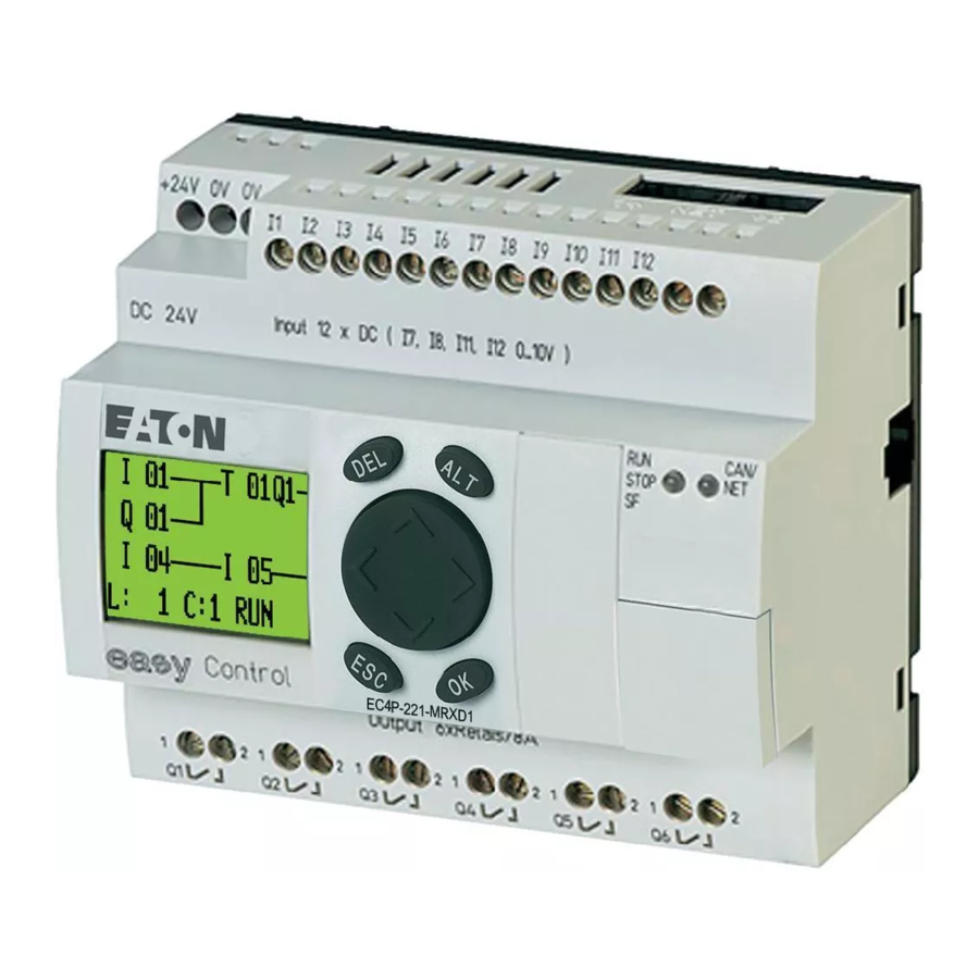
You use the programming software to create, test and document a project. Functions for analog processing, closed-loop control and function blocks such as timers, counters simplify programming. Type overview The EC4-200 series consists of a range of controllers that come with different displays and types of inputs/outputs. Type Features... - Page 12 05/06 AWB2724-1584GB...
-
Page 13: Inputs
05/06 AWB2724-1584GB 2 Setup Inputs Table 1: Type and number of inputs Digital 12 (I1…I12) 24 V DC Of which can be used 4 (I7, I8, I11, I12) 24 V DC/0…10 V as analog CAN/ STOP Inputs I7, I8, I11, I12 can also be used as analog inputs. They are selected in the user program by means of the appropriate syntax used in the PLC configurator. -
Page 14: Inputs Of The Rocker And Function Buttons
05/06 AWB2724-1584GB Setup Example: If you are using input I1 for a high-speed counter (16- Diagnostics inputs bit), I2 can be used for another high-speed counter (16-bit) but not The inputs I13, I14, I15, I16 provide you with additional for generating an interrupt. Inputs I3 and I4 likewise cannot be information: used for generating an interrupt. -
Page 15: Memory Card (Mcc)
05/06 AWB2724-1584GB Memory card (MCC) LED status indication for RUN/STOP/SF and CAN/NET Caution! Scan I15/I16 in the program. In the event of a short-circuit set the outputs to 0 in order to prevent the After power up, the CPU can switch to the following states, as thermal overload of the output circuit. -
Page 16: Real-Time Clock
<Programs l Moeller Software l easy Soft CoDeSys l Documentation l Automation Manuals>. The clock can be read or set using the browser command “getrtc”... -
Page 17: Can(Open) Interfaces
05/06 AWB2724-1584GB CAN(open) interfaces CAN(open) interfaces The PLC is provided with a CAN interface with two slots that are internally connected via terminals. Figure 7: CAN interfaces CANopen The CAN interface is designed as a CANopen interface in compliance with the CIA specification DS301V4.0. The PLC can be operated both as an NMT master as well as a CAN device on CAN networks. - Page 18 05/06 AWB2724-1584GB...
-
Page 19: Mounting On Top-Hat Rail
05/06 AWB2724-1584GB 3 Mounting Install the PLC in a control cabinet, a service distribution board or Mounting on top-hat rail in an enclosure so that the power supply terminals and other Place the device diagonally on the upper lip of the top-hat rail. terminals are protected against direct contact during operation. - Page 20 05/06 AWB2724-1584GB Figure 11: Screw fixing the EC4-200...
-
Page 21: Connecting The Power Supply
...V DC : +24 V Figure 12: Connect the power supply, the two 0 V terminals are connected internally! Die EC4-200 is protected against polarity reversal. The necessary connection data is provided in chapter “Technical data”, page 68. Cable protection Protect the supply cables with a miniature circuit-breaker or at least a 1A (slow blow) fuse (F1). -
Page 22: Connecting Digital Inputs
05/06 AWB2724-1584GB Installation Connecting digital inputs Ensure that the reference potential is galvanically connected. Connect the 0 V of the power supply unit for Use input terminals I1 to I12 to connect pushbutton actuators, the setpoint potentiometer and various sensors shown in switches or 3 or 4-wire proximity switches. -
Page 23: Temperature Sensor
05/06 AWB2724-1584GB Connecting analog inputs Temperature sensor 20 mA sensor A 4 to 20 mA (0 to 20 mA) sensor can be connected easily with an external 500 O resistor. +24 V H +24 V H –35...55 ˚C –35...55 ˚C 0...10 V 0...10 V 4...20 mA... -
Page 24: Connecting Pulse Transmitters/Incremental Encoders
05/06 AWB2724-1584GB Installation Connecting the incremental encoder Connecting pulse transmitters/incremental encoders Inputs I1 to I4 are designed so that high-speed signals from pulse L01 + transmitters/incremental encoders can be counted. L01 – The following connection options are possible: L02 + •... -
Page 25: Connecting Outputs
05/06 AWB2724-1584GB Connecting outputs Connecting outputs The relay or transistor outputs can be used to switch loads, such as fluorescent tubes, filament bulbs, contactors, relays or motors. Prior to installation observe the technical limit values and data for the outputs (a page 72, 73). Connecting relay outputs EC4P-221/222-MR…, EASY6..-DC-RE 24 V H 8 A... -
Page 26: Connecting Transistor Outputs
05/06 AWB2724-1584GB Installation Connecting transistor outputs EC4P-221/222-MT…, EASY6…-DC-TE F 10 A F 10 A 24 V f 2.5 A 24 V 0 V H f 2.5 A EC4P-221/222-MT… easy6…-DC-… + 24 V H 24 V H 0.5 A 0.5 A 24 V H 0.5 A 0.5 A... -
Page 27: Memory Card, Can/Easy-Net, Pc Connection
65. Attention! Figure 25: Adapter with memory card Protect the EC4-200 and memory card from electrostatic discharge in the following manner: Discharge yourself of electrostatic charge by touching a grounded surface To fit the memory card, press it until it snaps into position. - Page 28 05/06 AWB2724-1584GB...
-
Page 29: Keypad
05/06 AWB2724-1584GB 5 Operation The following chapter describes the operation of the buttons and Selecting or toggling between menu items the display on the front plate. Cursor Í Ú PROGRAM STOP PARAMETER Keypad SET CLOCK DEL: Delete Select or toggle ALT: Special function, status display ú... -
Page 30: Choosing The Main And System Menu
05/06 AWB2724-1584GB Operation Choosing the main and system menu Status display I 0.2..5 MO 02:00 WS Q ..34 . STOP password PROGRAM SECURITY Current STOPå RUN SYSTEM selection SET CLOCK STARTPARAMETER.. flashes in INFORMATION MENU LANGUAGE... menu 1st menu level 1st menu level Main menu System menu... -
Page 31: Menu Structure
05/06 AWB2724-1584GB Menu structure Menu structure Main menu without password protection You access the main menu by pressing OK. * Only use in STOP Main menu REPLACE? MEMORY->FLASH BOOTPROJECT PROGRAM BOOTPROJECT FLASH->CARD STOP å RUN RESET CARD->FLASH STORED SET CLOCK DELETE INFORMATION REPLACE? -
Page 32: Main Menu With Password Protection
05/06 AWB2724-1584GB Operation Main menu with password protection Enter Incorrect entry Main menu Password entry PASSWORD STOP RUN å Enter SET CLOCK INFORMATION Correct entry Status display PASSWORD MODE System menu The System menu is accessed by simultaneously pressing DEL and ALT. -
Page 33: Password Protection
05/06 AWB2724-1584GB 6 Description of settings All settings are made using the operating elements on the Press the OK button in order to protect the function or menu controller. (tick = protected). The password protection protects the program by default. At least one function or menu must be protected. -
Page 34: Changing Or Deleting The Password Range
05/06 AWB2724-1584GB Description of settings Password incorrect or no longer known PASSWORD ENTER PASSWORD STOP RUN å The PASSWORD… entry will flash. Have you entered an incorrect XXXXXX PASSWORD Press OK to enter the password password? SET CLOCK entry menu. Re-enter the password. -
Page 35: Changing The Menu Language
05/06 AWB2724-1584GB Changing the menu language Changing the menu language Startup behaviour Two menu languages can be selected. These can be set via the System menu. Setting the startup behaviour Language LCD display The following start options can be set via the menu: •... - Page 36 05/06 AWB2724-1584GB Use the cursor buttons Í and Ú CONTRAST: +1 LIGHTING å to move to the LIGHTING menu. Press the OK button. CONTRAST: +1 The backlight is LIGHTING deactivated. CONTRAST: +1 Press OK if you wish to LIGHTING å reactivate the backlight The tick å...
-
Page 37: Representation Of The Inputs/Outputs In The Configuration
05/06 AWB2724-1584GB 7 Configuration of the inputs/outputs (I/O) Representation of the inputs/outputs in the configuration Changing the folder function The direct addresses of the inputs/outputs are assigned symbolic Transistor Outputs n Relay Outputs names beforehand in the PLC configuration. The Transistor Outputs are displayed as the default PLC configuration. - Page 38 05/06 AWB2724-1584GB Figure 29: Selecting counters The submenu will appear: Select a counter type, sucha s 32-bit counter. “No Counter” will then be replaced by “32 Bit Counter”. Clicking the plus sign will display the inputs and outputs of the counter.
-
Page 39: General Technical Data
05/06 AWB2724-1584GB 8 Operation Startup behaviour with boot project on the memory card General technical data When the controller is switched on, a boot project on the memory card has priority over a project stored in the system memory. If Overview of memory sizes both projects are different, the boot project of the memory card is copied to the system memory and then started. - Page 40 05/06 AWB2724-1584GB Operation Power on Boot project on MMC? Boot project in the system memory (Flash)? Boot project in the system memory (Flash)? Boot project auf MMC = Boot procekt in the main memory (Flash)? Load boot project from system Load boot project from the MMC Load boot project from the memory (Flash) into the...
-
Page 41: Setting The Startup Behaviour In The Programming Software
05/06 AWB2724-1584GB Setting the startup behaviour in the programming software Setting the startup behaviour in the programming Program START/STOP software The startup behaviour setting determines the startup behaviour of Program start (STOP l RUN) the controller when the power supply is switched on. You can start the program in two ways: The setting can be made in the PLC configurator or via the operating elements of the controller. -
Page 42: Starting/Stopping The Program Via External Switch
05/06 AWB2724-1584GB Operation Starting/stopping the program via external switch Reset An external switch connected to an input can be used to start or You can carry out a reset via the PC in online mode or via the stop the processing of the program. Some additional program controller menu. -
Page 43: Behaviour Of Variables After Reset
05/06 AWB2724-1584GB Test and commissioning Behaviour of variables after Reset Forcing variables and inputs/outputs All the variables of a user program can be “forced” to assume Variable type fixed values. Forced local outputs are only switched to the Reset Non-retentive Retain periphery when the controller is in RUN status. -
Page 44: 16-Bit Counter
05/06 AWB2724-1584GB Operation Incrementing (Direction = FALSE): the counter counts up to the set reference value (PRESET). Once the reference value has been reached, this activates the configured interrupt which branches to a program routine (a page 45). The counter continues counting from zero when the next count pulse is received. -
Page 45: Explanation Of The Input/Output Signals (I/Q)
05/06 AWB2724-1584GB Incremental input Overview of input/output signals (I/Q) Program Incremental symbolic addresses Input encoder RefDone Signal A RefActive Zero Signal B Counter QuitZero Reference Signal RefMode RefWindowMode SetRefWindow Reference SetRefValue Window RefValue Reference switch Figure 36: Input/output signals of the incremental value counter Functions of the input/output signals Switching the CPU from HALT l RUN enables the counter: The incoming pulses are counted. -
Page 46: Referencing
05/06 AWB2724-1584GB Operation Referencing: System events In many positioning controllers, a reference point is approached at System events are: the start of positioning. For example, a tool slide is moved to its home position. In this position, a “reference switch” is closed, START START: User program start (cold and warm start) thus sending a signal to input I4. -
Page 47: Interrupt Inputs I1 To I4
05/06 AWB2724-1584GB System events Interrupt inputs I1 to I4 Timer interrupt Inputs I1 to I4 can be configured as interrupt inputs. An edge at You can create a program routine that is called at a fixed time the input generates an interrupt signal (a page 45), that calls interval. - Page 48 05/06 AWB2724-1584GB Operation Example • Create a program with a function call Create a program with the function TIMERINTERRUPTENABLE like in figure 41. • Creating the program routine Open the “Task Configuration” sub-directory with a double click in the “Resources directory”. Click here the “System Events”...
-
Page 49: Interrupt Processing
05/06 AWB2724-1584GB Interrupt processing Steps for interrupt processing Interrupt processing Define the interrupt properties: If an interrupt occurs, the program is interrupted and the program routine associated with the system event is processed. figure 44 Startup behaviour Select type shows a list of interrupt sources. TIMER INTERRUPT Call function TIMERINTERRUPTENABLE... -
Page 50: Generating And Transferring A Boot Project
05/06 AWB2724-1584GB Operation Figure 46: Interrupt edge selection Change over to the Task configuration and open the “System Events” folder. Figure 48: Assignment of interrupt source l POU Select the “Fastprog” POU and confirm with OK. Save the project. You can now test it. The variable “b”... -
Page 51: Storing The Boot Project On A Memory Card
The following prompt appears: Downloading/updating the operating system The EC4-200 enables you to replace the currently stored operating system (OS) with a more recent version. The latest OS version can be downloaded from the Moeller website at http:// www.moeller.net/support. -
Page 52: Transferring The Os From Pc To The Memory Card
05/06 AWB2724-1584GB Figure 53: Selecting the operating system file The target type and file version are displayed once the OS file is selected. Click the “Transfer Device” button. Figure 55: OS successfully transferred to the PLC Select the RS232 interface. In this window click the “Exit”... - Page 53 05/06 AWB2724-1584GB 9 Browser commands The PLC browser is a text-based controller monitor. This is where Table 7: Browser commands you enter commands in an entry line and send them as strings to Get a list of implemented commands. the controller in order to access specific information from it. The pinf Output project information response string is shown in a result window of the browser.
-
Page 54: Canload
05/06 AWB2724-1584GB canload setrtc Displays the load of the CANopen fieldbus. Sets or changes the date and/or the time in the controller. Example: Syntax: <setrtc_YY:MM:DD:DW_HH:MM:SS> Legend: Space The last two digits of the year (00 F YY F 99) Month (01 F YY F 12) Day (01 F DD F 31) Figure 56: “canload”... -
Page 55: Using Libraries
• Triggering interrupts • Sending/receiving data via the interfaces The libraries are located in the folders: • Lib_Common for all PLCs • Lib_EC4P_200 for the EC4-200 controller Using libraries Figure 57: Libraries, installing manually When you open a project, libraries “Standard.lib” and “SYSLIBCALLBACK.lib”... -
Page 56: Ec4-200 Specific Functions
05/06 AWB2724-1584GB Libraries, function blocks and functions EC4-200 specific functions EC_Util.lib library EC_Visu.lib library This library contains the functions shown in the illustration below: The EC_Visu.lib library contains function blocks for controlling the LCD display. Of the nine function blocks, only the function blocks “SetBacklight”, “SetContrast and GetDisplayinfo”... - Page 57 05/06 AWB2724-1584GB EC4-200 specific functions Display contrast data type (ENUM): Figure 65: ENUM VISULIB_ERROR Figure 63: Enum Display-Contrast Application example with GetDisplayInfo GetDisplayinfo: You can write the following program if the P1 button has to be Display information suppressed in the Status menu: This function shows the currently active menu level of the display.
- Page 58 05/06 AWB2724-1584GB...
-
Page 59: Communication Parameters Of The Pc
05/06 AWB2724-1584GB 11 PC n EC4-200 connection setup The communication parameters of both the PC and the PLC must Communication parameters (baud rate) of the CPU match in order to establish a connection between them. An The Open the PLC configuration. - Page 60 05/06 AWB2724-1584GB...
-
Page 61: Overview
COM_BAUDRATE: 4800,9600,19200,38400,57600 Startup.ini file already on it. CAN1_BAUDRATE: 10,20,50,100,125,250,500 Table 9: Example: STARTUP.INI file for EC4-200 CAN1_NODEID: 1-127 [STARTUP] CAN_ROUTINGID: 1-127 TARGET = EC4P-200 The parameters from the INI file have priority over parameters COM_Baudrate=38400 from the PLC configuration. -
Page 62: Changing Parameters
05/06 AWB2724-1584GB Defining system parameters via the STARTUP.INI file Changing parameters The parameters are retained until you enter the browser command “removestartupini” and then switch the controller off and on again. The controller will now operate with the parameters of the project. -
Page 63: Requirements
It is possible, for example, to load a program from the PC into the • Online modifications EC4-200 via a controller of the XC series. In this case, you assign • Program test (Debugging) the EC4-200 (target controller) with a routing Node ID. -
Page 64: Notes On Routing
“Blocksize” = dword:00020000 The default block size is 20000 (=128 Kbyte), the block size for Figure 73: Routing via XC…, EC4-200 the routing is 1000 (= 4 Kbyte). 1) The following applies to the Node ID of the Device function and the... -
Page 65: Procedure
125 Kbit/s in order to ensure rapid data transfers. Figure 76: CAN device parameters Figure 74: Routing settings of the EC4-200 target controller The following illustrations indicate, regardless of the routing settings, where to enter the baud rate and the Node ID of the PLCs which have been configured as masters or devices. -
Page 66: Plc Combinations For Routing
XC200 with Node ID 2 Figure 79: Setting the target ID of the target PLC c Controller with node ID 3, e.g. XC100,XC200,XC121, XN-PLC, EC4-200. PLC combinations for routing You have connected the PC to the PLC with Node ID “2” and want The following PLCs support routing: to access the target PLC with Node ID “3”. - Page 67 05/06 AWB2724-1584GB 14 RS 232 interface in Transparent mode In Transparent mode, data is exchanged between the EC4-200 and data terminal devices (e.g. terminals, printers, PCs, measuring devices) without any interpretation of the data. For this the serial interface RS 232 (COM1) must be switched to Transparent mode via the user program.
- Page 68 05/06 AWB2724-1584GB...
-
Page 69: Appendix
05/06 AWB2724-1584GB Appendix Calculating the cable length for a known cable resistance CAN/easy-NET network If the resistance of the cable per unit of length is known (resistance per unit length R’ in O/m), the entire cable resistance R must not exceed the following values. -
Page 70: Example Program For Plc Start/Stop Using External Switch
05/06 AWB2724-1584GB Appendix Example program for PLC START/STOP using external switch The SysLibPlcCtrl.lib library contains the function SysStartPlcProgram required for the start, and the function SysStopPlcProgram required for the stop. In this case, the startup behaviour of the controller must be set to WARM START in the PLC configurator under <Other Parameters l Figure 83: Declaring global variables Settings>! -
Page 71: Dimensions And Weight
05/06 AWB2724-1584GB Dimensions and weight Dimensions and weight Dimensions W x H x D [mm] 107.5 x 90 x 72 with adapter for MMC 107.5 x 90 x 79 [inches] 4.23 x 3.54 x 2.84 with adapter for MMC 4.23 x 3.54 x 3.11 Space units (SU) width Weight [lb]... -
Page 72: Technical Data
05/06 AWB2724-1584GB Appendix Technical data Climatic environmental conditions (Cold to IEC 60068-2-1, Heat to IEC 60068-2-2) Ambient temperature °C, (°F) –25 to 55, (–13 to 131) Installed horizontally/vertically Condensation Prevent condensation with suitable measures LCD display (reliably legible) °C, (°F) 0 to 55, (–32 to 131) Storage/transport temperature °C, (°F) - Page 73 05/06 AWB2724-1584GB Technical data Tools and cable cross-sections Solid, minimum to maximum 0.2 to 4 22 bis 12 Flexible with ferrule, minimum to maximum 0.2 to 2.5 22 bis 12 Factory wiring Slot-head screwdriver, width 3.5 x 0.8 inch 0.14 x 0.03 Tightening torque Memory specifications Program code...
- Page 74 05/06 AWB2724-1584GB Appendix CAN(open)/easy-NET Data transfer rate Kbit/s 10, 20, 50, 100, 125, 250, 500 Default: 125 Potential isolation from inputs/outputs/power supply Bus termination resistor EASY-NT-R plug (incl. bus terminating resistor 120 O) Terminations 2 x RJ45, 8pole CANopen operating mode Station Number max.
- Page 75 05/06 AWB2724-1584GB Technical data Delay time for “0” to “1” I1 to I4 0,02 I5 to I12 0,25 Delay time for “1” to “0” I1 to I4 0,02 I5 to I12 0,25 Cable length (unshielded) Additional input functions Inputs for analog signals Number 8 (I7, I8, I11, I12) Signal range...
- Page 76 05/06 AWB2724-1584GB Appendix Relay outputs Number of outputs Parallel switching of outputs to increase performance Not permissible Protection of an output relay Miniature circuit-breaker B16 or fuse (slow-blow) Electrical isolation Safe isolation V AC Basic insulation V AC Mechanical lifespan Switch 10 x 10 operations...
-
Page 77: Transistor Outputs
05/06 AWB2724-1584GB Technical data Relay switching frequency Mechanical operations Switch 10 mill. (10 operations Mechanical switching frequency Resistive lamp load Inductive load Transistor outputs Number of outputs Rated voltage U V DC Permissible range V DC 20.4 to 28.8 Residual ripple Supply current On “0”... - Page 78 05/06 AWB2724-1584GB Appendix Parallel connection of outputs with resistive load; inductive load with external suppression circuit (a section “Connecting transistor outputs”, page 22); combination within a group Group 1: Q1 to Q4 Group 2: Q5 to Q8 Maximum number of outputs Total maximum current Attention! Outputs connected in parallel must be switched at the...
-
Page 79: Index
05/06 AWB2724-1584GB Index Addressing, PLC on CANopen fieldbus ... . . 60 Data access, to MMC ......11 Analog inputs, connecting . - Page 80 05/06 AWB2724-1584GB Index Keypad ........25 Real-time clock .
- Page 81 05/06 AWB2724-1584GB Index Variables Behaviour after Reset ..... . 39 Behaviour on startup ..... . 37 Weekday setting .
- Page 82 05/06 AWB2724-1584GB...
Need help?
Do you have a question about the EC4-200 and is the answer not in the manual?
Questions and answers