Table of Contents
Advertisement
Advertisement
Table of Contents

Related Manuals for Maxwell RC12


Summary of Contents for Maxwell RC12
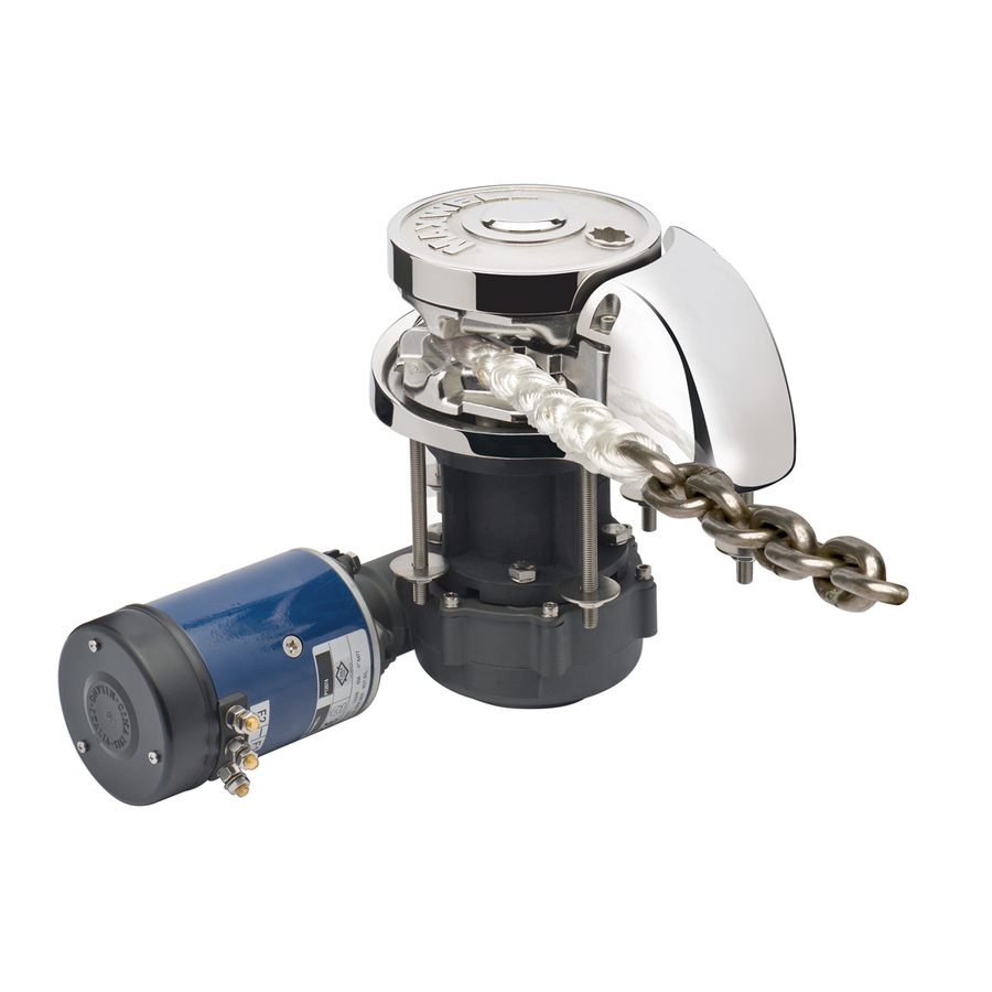
- Page 1 RC12 Vertical Rope/Chain Windlass...
- Page 2 Ó Copyright Maxwell Marine International, 2008. All rights reserved. Maxwell Marine International reserves the right to make engineering refinements on all products without notice. Illustrations and specifications are not binding as to detail. Part No: P103133 23/01/12...
-
Page 3: Table Of Contents
Additional Resources The following resources are included at the back of this manual: Deck Cutout Details Warranty Form Contact Details (on back cover) Note: For your nearest retailer, service agent or representative please refer to our website www.maxwellmarine.com RC12 Windlass... -
Page 4: Preliminary Information
Preliminary Information Introduction Congratulations on your purchase of a Maxwell windlass. Please read these instructions carefully to enable you to correctly install and maintain the windlass for years of trouble-free operation. Note Failure to follow the correct installation, operation or maintenance instructions will jeopardise your safety and could invalidate the warranty. -
Page 5: Important Safety Information
Where this has occurred, repair by cutting away the affected portion and re-splice. Tip: The rope can be swapped end-for-end to extend its life. · Do NOT use the windlass to haul a person up a mast. RC12 Windlass... -
Page 6: Parts Of Thetopworks
Windlass Parts Fig 1: Windlass Parts RC12 Windlass... - Page 7 7037 Spring ACW 7436 Pressure Arm 7435 Deckplate CW 7430 Deckplate ACW 7431 Gasket 7515 Stud - 90TDC 5225 Stud - 190TDC 7482 Washer 3843 Spring Washer SP0466 Nut - M10 SP0371 Spring 7458 Pawl 7456 Washer SP0413 RC12 Windlass...
- Page 8 Cap screw -M8 x 25 SP0158 Plug SP3519 Bush SP3518 Screw -M10 x 35 SP3221 Pawl 7457 Bush 7480 O-ring SP2785 Cap screw -M6 x 16 SP0170 7465 Key - Capstan 3150 CW - clockwise ACW - anticlockwise RC12 Windlass...
-
Page 9: Parts Of The Bottomworks
Bottomworks /Handle list Fig 2: Bottomworks/handle parts RC12 Windlass... - Page 10 Bi-square handle P103865 Emergency handle - LP CW P103319 Emergency handle - LP ACW P103323 Emergency handle -Capstan CW P103320 Emergency handle -Capstan P103324 Some listed parts are sold as a kit only. CW - clockwise ACW - anticlockwise RC12 Windlass...
-
Page 11: Ordering Spare Parts
Ordering Spare Parts When ordering spare parts, please refer to the parts list above and quote the following details. Windlass Model RC12 10mm - 3/8” RC12 12/13mm – 1/2” 90TDC 190TDC Serial number Power supply Part details Part number Description Quantity Refer back cover for web details. - Page 12 16mm - 20mm (5/8”- 3/4”) rope / 10mm (3/8”) chain ACW = P103321 16mm - 20mm (3/4”) rope / 12mm/13mm (1/2”) chain ACW = P103322 THE WINDLASS SHOULD BE USED IN CONJUNCTION WITH A MAXWELL CHAIN STOPPER, OR SNUBBER, OF THE APPROPRIATE SIZE. RC12 Windlass...
-
Page 13: Rope And Chain Selection Guide
The bow roller should have a vertical groove to suit the profile of the chain. This will align the chain so that it enters the chainwheel without twisting. RC12 Windlass... -
Page 14: Installation
Refer to drawing in this Manual and identify all parts. If any parts are damaged or missing, contact your Maxwell distributor. Some smaller parts might not be assembled on the windlass by the factory, but supplied in a plastic bag in the packing case. - Page 15 Insert the cap into the clutch nut. When tightening the cables to the motor, ensure the lower nut (A) is secure against turning when tightening the upper nut (B). This will prevent damage occurring within the motor. Complete wiring as per diagram on page18. RC12 Windlass...
- Page 16 Fig 3: Motor Orientation RC12 Windlass...
- Page 17 Groove Looking from above, align the pressure arm with the hole for the capscrew. Hole and spring alignment While holding the pressure arm in this position, assemble the capscrew. RC12 Windlass...
- Page 18 We recommend, after completing installation, you spray the top works of the windlass with CRC 3097 “long life” and wrap the windlass with plastic film and tape. RC12 Windlass...
-
Page 19: Wiring Instructions
For safe operation, the footswitches must be at least 500 mm (20") from the windlass. The below-deck part of the footswitch must be in a dry environment and installed per instructions. The arrows on the footswitches should be arranged to indicate the direction of operation. RC12 Windlass... - Page 20 Wiring schematic 1 Battery 2 Breaker/Isolator 3 Manually resettable breaker 4 Solenoid Pack 5 Up Foot Switch 6 Down Foot Switch 7 Remote control panel 8 Motor Series Wound Motor RC12 Windlass...
- Page 21 Battery to Winch Then Back to Battery mm² mm² Up to 27 m (88’) 27m – 43m (88’ – 141’) * Engine room size correction factor is based on the ambient temperature of the engine room to be 60° C. RC12 Windlass...
- Page 22 RC12 Windlass...
- Page 23 RC12 Windlass...
-
Page 24: Operation
(or press the "Down" footswitch if fitted). 3. Pay out sufficient rope/chain to set the anchor. 4. Watch as the rope/chain is being fed out. Any jam might cause damage to the windlass. RC12 Windlass... -
Page 25: Raising The Anchor
Tip: Mark the chain at suitable intervals with coloured line, or purchase and install a Maxwell AutoAnchor rope/chain counter. Note To avoid applying the full force of the windlass to the bow fitting when docking the anchor, adjust the clutch nut so that there is some slippage when docking the anchor. - Page 26 Pawl should be engaged with chainwheel preventing chainwheel from freefalling. Insert the clutch handle into the clutch nut and turn anticlockwise to loosen the clutch. Using 5mm Allen key remove cap, washer, screw, clutch nut, washer, key and capstan. RC12 Windlass...
- Page 27 Ensure that emergency handle pawl is engaged with upper chainwheel. Replace clutch nut. Rotate clockwise to pull in the line. Ensure that self locking mechanism is engaged with bottom chainwheel before you remove handle. Above images are taken of the clockwise windlass. RC12 Windlass...
-
Page 28: Using The Warping Drum
Make sure that you do not operate the footswitch accidentally while putting extra turns on the capstan. · Keep your fingers clear of the capstan. · Do not put so many turns on the drum that easing the load on the tail will not allow the rope to slip on the drum. RC12 Windlass... -
Page 29: Maintenance
Re-assemble in reverse order. IMPORTANT – care must be taken to ensure the key/keys are properly seated in the shaft. Clean the Windlass with a cloth damp with Kerosene (paraffin). Spray preferably with CRC3097 “Long Life” or alternatively, CRC6-66 or WD40. Polish off with a clean non-fluffy cloth. RC12 Windlass... - Page 30 Every 3 months, check level of oil in gearbox using the sight glass. If necessary top up . We recommend that the gearbox be removed and serviced by an authorised Maxwell service technician every three years. Visit our website (www.maxwellmarine.com) for a list of service centres and agents.
-
Page 31: Trouble Shooting Guide
The splice may be worn or frayed. Re-splice the rope to the chain. · The rope or splice may be catching on the hole through the deck. Make sure the hole is free from rough edges. · The chain may be twisting. Install a swivel between the chain and anchor. RC12 Windlass... -
Page 32: Reference Information
Reference Information Specifications GENERAL Model RC12 10mm -3/8" RC12 12mm/13mm-1/2" Max. Pull Rating 1134kg (2500 lbs) 1590kg (3500 lbs) Chain Size 10mm (3/8") short link 12mm/13mm (1/2")short link Rope Size 16mm-20mm (5/8"-3/4”) 16mm-20mm (5/8"-3/4”) Chain Speed (Normal Working Load) 24m/min (79 ft/min) -
Page 33: Dimensions
Dimensions Figure 6: Dimensions - DC motors RC12 Windlass... - Page 34 Figure 7: Dimensions - Hyd motors RC12 Windlass...
- Page 35 RC12 Windlass...
- Page 36 RC12 Windlass...
- Page 37 Maxwell equipment. This Warranty sets out your specific legal rights allowed by Maxwell, these may be varied by the laws of different countries. In addition, the purchaser may also have other legal rights which vary from country to country.
Need help?
Do you have a question about the RC12 and is the answer not in the manual?
Questions and answers