
Subscribe to Our Youtube Channel
Related Manuals for Enerpac LAT Series


Summary of Contents for Enerpac LAT Series
- Page 1 LAT-SERIES BOLTING PUMP INSTRUCTION SHEET LA-SERIES BOLTING PUMP MODEL LA2504TX-QR INSTRUCTION SHEET L4402 REV. B 05/20 MODEL LA2504TX-QR...
-
Page 2: Table Of Contents
TABLE OF CONTENTS INTRODUCTION ............................3 SAFETY ............................... 3 PRODUCT DATA ............................5 MAJOR FEATURES AND COMPONENTS ....................7 PRODUCT DESCRIPTION .......................... 8 PREPARATION FOR USE ........................... 8 OPERATION .............................. 11 MAINTENANCE ............................13 TROUBLESHOOTING ..........................17 L4402... -
Page 3: Introduction
/ or damage to other property. use with hydraulic torque wrenches in industrial bolting Enerpac cannot be responsible for any damage or injury applications. Refer to Sections 4.0 and 5.0 of this manual from unsafe use, lack of maintenance, or incorrect for additional product information and details. - Page 4 • Immediately replace worn or damaged parts. Use only genuine Enerpac parts from approved NOTICE distributors or service centers. Enerpac parts have been engineered for proper fit and function and safe • Hydraulic equipment must only be serviced by a operation.
-
Page 5: Product Data
(1 male, 1 female) (.500-14) Enerpac Spin-On hydraulic couplers are included with pump. Pump hydraulic port thread size is 1/4” NPTF. Approximate usable oil capacity of pump hydraulic reservoir. Pump total oil capacity (including reservoir and pump element housing) is approximately 0.8 gallons [3.0 liters]. - Page 6 3.3 External Dimensions - Model LA2504TX-QR Dimension Item inch 17.1 14.8 15.0 (pendant cable) L4402...
-
Page 7: Major Features And Components
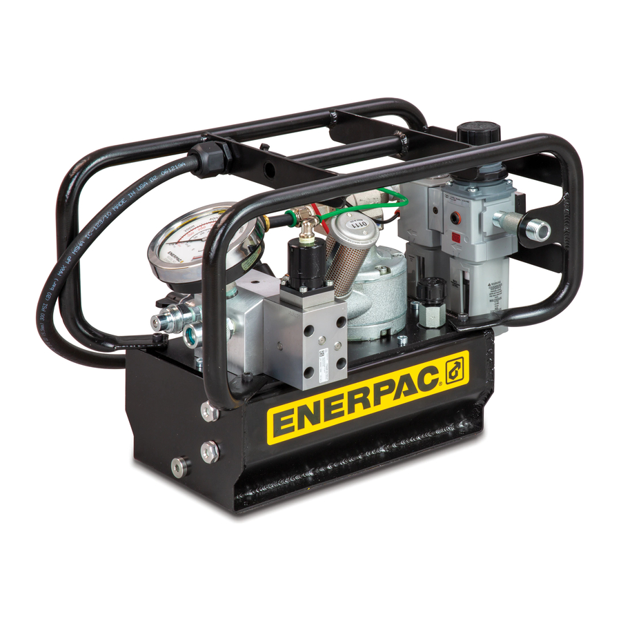
4.0 MAJOR FEATURES AND COMPONENTS Key: 1. Hydraulic Pressure Gauge 2. Roll Cage 3. Hydraulic Hose Port B 4. Oil Sight Glass (top) 5. Oil Sight Glass (bottom) 6. Oil Drain Plug 7. Hydraulic Hose Port A 8. Hyd. Relief Valve (user-adjustable) 9. -
Page 8: Product Description
The hydraulic reservoir is pre filled with oil at the factory. 5.1 Introduction However, the oil level should always be checked as a The Enerpac LAT-Series air-powered bolting pump is precaution before running the pump. See Figure 3 and designed for use with hydraulic torque wrenches rated at refer to the following steps: 10,000 psi [690 bar] maximum operating pressure. - Page 9 The pump is supplied with coupler halves pre- NOTICE installed in the pump hydraulic ports. These coupler halves are compatible with Enerpac THQ Series torque wrench hoses. Figure 4: Air Inlet Connection Remove dust caps from pump couplers “A” and “B”.
- Page 10 proper wrench operation and may result in high pressure The air lubricator must be periodically refilled NOTICE oil leakage and/or detachment of the hose under pressure. with the proper lubricant. Maintaining the lubricator oil Skin penetration and serious personal injury could occur. level is critical to the life of the air motor.
-
Page 11: Operation
To check for proper air lubrication levels, hold NOTICE a mirror near the pump air muffler exhaust outlets. If a heavy oil film develops, reduce the drip rate as required. GREEN BUTTON 7.0 OPERATION • Press and hold to 7.1 Pre Start-up Checklist start pump and advance wrench. - Page 12 7.4 Removing Air from Hydraulic System Key: When the torque wrench is first connected to the pump, 1. Adjustment Knob or after a different torque wrench is connected, air may 2. Locknut become trapped in the hoses and components. To ensure smooth and safe operation, remove air by cycling the torque wrench several times without load.
-
Page 13: Maintenance
When adding oil or refilling the hydraulic reservoir, additional 10 seconds. NOTICE use only Enerpac HF hydraulic oil. Use of other oils may Press and hold the green ON/ADV button. As the result in damage to pump components and may void the button remains depressed, allow the pump to run for Enerpac product warranty. - Page 14 • If the magnet is missing, order a replacement magnet from your Enerpac distributor. Refer to the pump repair parts sheet for part number Operation of pump without magnet installed may...
- Page 15 Key: 1. Roll Cage & Filter/Regulator/Lubricator 2. Capscrew 3. Gasket Key: 4. Pump & Reservoir Assembly 1. Capscrew 2. Gasket Figure 13: Reservoir Inspection & Cleaning (View 1 of 2) 3. Pump, Cover Plate & Air Motor Assembly 10. Using a clean lint free rag, wipe the oil intake screen on each of the three piston blocks.
- Page 16 8.4 Air Filter/Regulator See Figure 17. • Periodically check the filter bowl for water. If water is visible in the bowl window, turn the drain valve at bottom of filter bowl to drain the water. • Replace the filter bowl if it becomes damaged, crazed or cracked •...
-
Page 17: Troubleshooting
• Periodically clean the air lubricator bowl. USE 9.0 TROUBLESHOOTING MILD SOAP AND WATER ONLY! DO NOT use Only qualified hydraulic maintenance personnel with cleansing agents such as acetone, benzene, carbon appropriate skills and training should be permitted tetrachloride, gasoline, toluene, etc., which will to service the pump or system components. - Page 18 Troubleshooting Chart (continued) Symptom Possible Cause Solution 4. Low oil flow. a. Low air pressure and/or flow. Increase air pressure as required. Verify that air system is capable of producing the minimum required pressure and flow. Refer to Section 6.3. b.
- Page 19 NOTES _______________________________________________________________________________________ _______________________________________________________________________________________ _______________________________________________________________________________________ _______________________________________________________________________________________ _______________________________________________________________________________________ _______________________________________________________________________________________ _______________________________________________________________________________________ _______________________________________________________________________________________ _______________________________________________________________________________________ _______________________________________________________________________________________ _______________________________________________________________________________________ _______________________________________________________________________________________ _______________________________________________________________________________________ _______________________________________________________________________________________ _______________________________________________________________________________________ _______________________________________________________________________________________ _______________________________________________________________________________________ _______________________________________________________________________________________ _______________________________________________________________________________________ _______________________________________________________________________________________ _______________________________________________________________________________________ _______________________________________________________________________________________ _______________________________________________________________________________________ L4402...
- Page 20 © 2020 Enerpac, All Rights Reserved.
Need help?
Do you have a question about the LAT Series and is the answer not in the manual?
Questions and answers