Lanberg FF01 37U Series User Manual
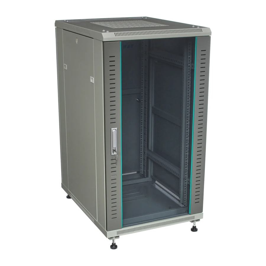
19" rack cabinets
Hide thumbs
Also See for FF01 37U Series:
- User manual (20 pages) ,
- User manual (20 pages) ,
- User manual (20 pages)

Related Manuals for Lanberg FF01 37U Series

Summary of Contents for Lanberg FF01 37U Series
- Page 1 19” Rack cabinets FF01 37U, 42U, 47U, 800*800, 800*1000 series Szafy stojące 19” seria FF01 37U, 42U, 47U, 800*800, 800*1000 User’s manual Instrukcja obsługi 2021/08...
- Page 2 Lanberg brand owners reserve the right to make changes to this manual at any time without notice. The products mentioned in this manual, including the documentation, are the property of the Lanberg brand owners and its licensors.
- Page 3 • Place the device on a stable, dry surface in a well-ventilated place. Leave at least 100 mm of free space around it to ensure adequate ventilation. • The device is designed to work only in a controlled environment (controlled temperature and humidity according to the data in the specification, indoors, without conductive pollution present [dust, flammable gases, corrosive substances, etc.]). Lanberg © 2015-2021...
- Page 4 1 pc. Item I Mounting rails 4 pcs 4 pcs Item X Vertical mounting rails 2 pcs 2 pcs Item Y Spacers 12 pcs Flat 3 pcs Item J Top panel cap With a groove 4 pcs Lanberg © 2015-2021...
- Page 5 30 pcs Item T M6 Snap nut 48 pcs 50 pcs Item U M6x12 Allen screw 72 pcs 76 pcs Item Z M6x12 nut 24 pcs 25 pcs M6 Additionally screw Item V 20 pcs 20 pcs and nuts Lanberg © 2015-2021...
- Page 6 Step 1. Remove the front door lock (item N), the side panel locks and the rear panel lock (item O), the components are in pack 1/3. Then remove the front glass door (item A), back panel (item B) and side panels (item C) from pack 2/3. At this stage we start by fitting locks to the above components. Lanberg © 2015-2021...
- Page 7 (item D) and then use an M8 Allen screw (item Q) and M8 flange nuts (item P) to join them together. Step 4a. Fit an M6 snap nut (item T) Snap nut M6 in the square hole in the frame (indi- (item T) cated in the figure). Lanberg © 2015-2021...
- Page 8 Use an M6 Allen screw (item U) and an M5 self-tapping screw (item R) to fix the crossbar. Step 6. Use an M6 Allen screw (item U) to attach the spacers (item Y) to the crossbars (item G). Allen head bolt M6 (item U) Lanberg © 2015-2021...
- Page 9 Nut M6x12 M6x12 (item Z) (item U) Step 8. Use M5 self-tapping screws (item R) to install the vertical mounting rails (item X) to the spacers (item Y). Krok 8a. Place the covers on the rails. Self-Tapping Screw M5 (item R) This side up Lanberg © 2015-2021...
- Page 10 Step 10. Prepare M5 self-tapping Step 11. Prepare and use an M4 self- screws (item R), then use them to attach tapping screw (item S) to fix the top the fan shelf (item H) to the RACK frame panel cap (item J). (item D). Self-tapping screw M5x10 (item R) Self-tapping screw M4x8 (item S) Lanberg © 2015-2021...
- Page 11 Self-tapping screw M4x8 (item S) Step 13. Prepare and place the door spacers (item W) for the front door and rear panel (items A and B) in the appropriate places. Fit the side panels (item C) at the very end. Lanberg © 2015-2021...
- Page 12 Właściciele marki Lanberg zastrzegają sobie prawo do wprowadzania zmian w niniejszej instrukcji w dowolnym czasie i bez uprzedzenia. Produkty o których mowa w niniejszej instrukcji, w tym dokumentacja, są własnością właścicieli marki Lanberg i ich licencjodawców.
- Page 13 • Urządzenie przeznaczone jest do pracy tylko i wyłącznie w kontrolowanym środowisku (kontrolowana temperatura oraz wilgotność otoczenia zgodnie z informacjami zawartymi w specyfikacji, praca wewnątrz budynku, bez zanieczyszczeń przewodzących [zapylenia, palnych gazów, substancji powodujących korozje etc.]). Lanberg © 2015-2021...
- Page 14 1 szt. Element I Szyna montażowa 4 szt. 4 szt. Szyna montażowa Element X 2 szt. 2 szt. pionowa Dystans szyn Element Y 12 szt. montażowych Płaska 3 szt. Element J Zaślepka panelu Z wyżłobieniem 4 szt. Lanberg © 2015-2021...
- Page 15 Element T M6 Nakrętka zatrzaskowa 48 szt. 50 szt. Element U M6x12 Śruba imbusowa 72 szt. 76 szt. Element Z M6x12 Nakrętka 24 szt. 25 szt. M6 Dodatkowo śruba Element V 20 szt. 20 szt. i nakrętka Lanberg © 2015-2021...
- Page 16 Krok 1. Wyjmij zamek drzwi przednich (element N), zamki paneli bocznych oraz panelu tylnego (element O), elementy znajdują się w opakowaniu 1/3. Następnie wyjmij przednie szklane drzwi (element A), tylny panel (element B) oraz panele boczne (element C) z opakowania 2/3. Na tym etapie rozpoczynamy od montażu zamków do powyższych elementów. Lanberg © 2015-2021...
- Page 17 śruby imbusowej (element oraz nakrętek kołnierzowych M8 (element P) aby je połączyć razem. Krok 4a. Zamontuj nakrętkę za- Nakrętka trzaskową M6 (element T) w ramie zatrzaskowa M6 w kwadratowym otworze (wskazany (element T) na rysunku). Lanberg © 2015-2021...
- Page 18 Do zamocowania listwy użyj śruby imbusowej M6 (element U) i wkrętu samogwintującego M5 (element R). Krok 6. Użyj śruby imbusowej M6 (element U) aby zamocować dystanse (element Y) do listw poprzecznych Śruba imbusowa M6 (element G). (element U) Lanberg © 2015-2021...
- Page 19 Krok 8. Użyj śrub samogwintujących M5 (element R), aby zainstalować szyny montażowe pionowe (element X) do dystansów (element Y). Następnie załóż pokrywy Krok 8a. Załóż pokrywę. na szyny. Śruba samogwintująca M5 (element R) Tą stroną do góry Lanberg © 2015-2021...
- Page 20 M5 (element R), następnie użyj ich do samogwintująceJ M4 (element S), aby zamocowania półki wentylatora (element zamocować zaślepkę panelu górnego H) do ramy szafy RACK (element D). (element J). Śruba samogwintująca M5x10 (element R) Śruba samogwintująca M4x8 (element S) Lanberg © 2015-2021...
- Page 21 (element M) (12 szt.). Śruba samogwintująca M4x8 (element S) Krok 13. Przygotuj i umieść odpowiednich miejscach dystanse drzwi (element W) dla przednich drzwi oraz tylnego panelu (element A i B). Boczne panele (element C) zamontuj na samym końcu. Lanberg © 2015-2021...
- Page 22 E-mail: support@lanberg.pl | support@lanberg.eu www.lanberg.pl | www.lanberg.eu...
Need help?
Do you have a question about the FF01 37U Series and is the answer not in the manual?
Questions and answers