Table of Contents
Advertisement
Quick Links
Advertisement
Table of Contents

Related Manuals for TeachLogic VoiceLink Plus


Summary of Contents for TeachLogic VoiceLink Plus
- Page 1 VoiceLink owner’s manual Infrared Wireless Microphone System...
- Page 2 VoiceLink owner’s manual...
- Page 3 notes Date of Purchase: Model Number: Serial Number: Notes:...
- Page 4 We appreciate your confidence by your selection of our product. It is TeachLogic’s intent to uphold that confidence by providing factory assistance and dealer support.
- Page 5 Read Instructions All safety and operation instructions should be read before operating this TeachLogic product. Retain Instructions Safety and operating instructions should be kept for future reference. Water & Moisture certifications This product should not be operated near water.
-
Page 6: Table Of Contents
VoiceLink owner’s manual transmitter table of contents About Infrared.............. Product Description............. VoiceLink Plus Components........Corner Sensor............... Microphone/Transmitters........Drop-in Battery Chargers......... Installation of Receiver/Amplifier......14–15 Installation of Speakers........Installation of Sensor........... System Operation............18–19 Wiring to Projector System........ Troubleshooting............21–23 Specifications............ -
Page 7: About Infrared
“What’s said in detects the sequential signal and the electronic the room, stays in circuitry in the VoiceLink PLUS converts that se- quential signal into a line level analog audio signal. the room” Now that audio signal can be fed into an amplifier. -
Page 8: Product Description
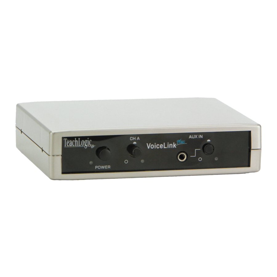
VoiceLink owner’s manual product description The VoiceLink PLUS is a complete classroom sound system. It includes an infrared wireless micro- phone/transmitter receiver and a 20 watt power amplifier. A corner sensor senses the infrared signal emitted from the microphone/transmitter and sends the voice signal to the receiver. The receiver can also accept an input from another au- dio source such as an iPod™, Computer, DVD, or... -
Page 9: Voicelink Plus Components
VoiceLink plus system The VoiceLink PLUS system is comprised of a microphone/transmitter, either the Crescent (IRT- 30), the Pendant (IRT-89), or a Body-Pack with an external microphone (IRB-30) for voice transmis- sion to a corner sensor (IWS-30). The sensor sends the signal to the receiver/mixer (IMA-100). -
Page 10: Corner Sensor
VoiceLink owner’s manual IWS-35 corner sensor The corner sensor is the component that receives the infrared transmission from the microphone/ transmitter and sends the signal to the receiver via a dual shielded cable. The sensor has 2 large receiving diodes. The receiving pattern of the sen- sor is like an elliptical shape cone about 90º... - Page 11 infrared microphone/transmitters The infrared microphone/transmitter is comprised of a microphone input, signal processing circuits and several emitting diodes that transmit the vocal signal to the sensor. The microphone/transmitter can be the Crescent or Pendant style worn around neck, or Body-Pack clipped to your waist with your choice of microphone (Lapel, Collar, or Head- band).
- Page 12 VoiceLink owner’s manual IRT-30 crescent transmitter The Crescent is a lightweight microphone/ transmitter designed to be worn under the chin suspended by an adjustable lanyard. The Crescent shape was designed for efficient performance and user comfort. The dual internal microphones render optimum voice pick up and quality vocal reproduction.
- Page 13 IRT-89 pendant transmitter The Pendant Transmitter (IRT-89) is a complete self-contained unit with a built-in microphone. It is worn around the neck, suspended by an adjustable lanyard to position for optimum performance and comfort. The transmitter is easily unclipped from the lanyard for handheld use and student partici- pation.
- Page 14 VoiceLink owner’s manual...
- Page 15 IRB-30 body-pack transmitter The Body-Pack Transmitter (IRB-30) is usually worn on the waistband with an external microphone plugged in, i.e., Lapel (LM-835), Collar (CM-835) or Headband (HBM-935). Or with a lanyard and a Plug-in microphone capsule (LM-300) plugged into the top, it can be worn as a pendant microphone/ transmitter.
- Page 16 VoiceLink owner’s manual optional microphones for body-pack transmitter Any of the microphones below may be used with the Body-Pack Transmitter. LM-835 lapel microphone The Lapel Microphone (LM-835) is a small capsule microphone with a spring clip for securing it on to a clothing edge.
-
Page 17: Microphone/Transmitters
ULM-835 ultra-lite microphone The Ultra-Lite Microphone (ULM-835) is a minia- ture boom style microphone supported by a wire around the left ear. The unidirectional microphone element renders excellent vocal quality and maximum clarity. Its lightweight and miniature size make it comfortable and inconspicuous. It is avail- able in either beige or black. -
Page 18: Drop-In Battery Chargers
VoiceLink owner’s manual drop-in battery chargers The battery chargers are specifically designed to recharge NiMH batteries at an optimum rate for maximum operating capacity and extended service life. The chargers feature a recy- cle function, which is used to restore the battery charge capacity and extend their service life. BRC-50 The BRC-50 charger recharges the Crescent (IRT-30) and Body-Pack transmitter (IRB-30). -
Page 19: Installation Of Receiver/Amplifier
installation of receiver/amplifier Location of the receiver/amplifier is primarily determined by user accessibility, availabil- ity of an electrical outlet, location of the auxiliary input source, and routing of the sensor and speaker cables. The receiver/amplifier can be placed on desk top, mounted on the wall, mounted on top or under a shelf using the mounting flanges and hardware provided. -
Page 20: Installation Of Speakers
VoiceLink owner’s manual installation of speakers Two wall mount or ceiling speakers can be powered by the receiver/amplifier. It has two amplifiers (10 watts ea.). One speaker will be connected to each amplifier. Optional: Two additional speakers can be powered by the amplifier. Connect two speak- ers in parallel. - Page 21 installing SP-2000 wall mount speakers • First observe the shape of the room: ceiling height, door locations, windows, mounting sur- face, and seating area • Ordinary installation would be to locate the speakers on each side wall approximately even with the front row of listeners •...
-
Page 22: Installation Of Sensor
VoiceLink owner’s manual installation of IWS-35 corner sensor The corner sensor is a critical component of the system for reliable operation of the wireless transmitter. It receives the infrared signal and sends it to the receiver/amplifier. Its location is very important. Corner installation provides the best performance. The receiving pattern of the sensor is like an elliptical shape cone about 90º... -
Page 23: System Operation
operating the system We will test of the system with the wireless microphone/transmitter purchased with the system and an external auxiliary source i.e., an iPod™, computer, or DVD player. system operation • Set volume control of receiver and microphone to “Minimum” •... -
Page 24: Wiring To Projector System
Connect the speaker outputs to installed speakers AUDIO OUT • Turn “on” VoiceLink Plus and Video Projector • Set “AUX IN” control on VoiceLink Plus to 2 o’clock position REMOTE • SENSOR With microphone turned “on”, speak and adjust microphone volume using “MIC” volume control on VoiceLink Plus •... - Page 25 Speaker AUX IN AUDIO AUDIO AUDIO IN 1 IN 2 IN 3 Video Projector DVD Player MP3 Player Computer...
-
Page 26: Troubleshooting
VoiceLink owner’s manual troubleshooting Problem Solution System is turned • Verify AC power; the Red “on” but there is no LED lights when turned sound “on” Check if system has • been unplugged Check circuit breaker • Call maintenance for •... -
Page 27: Specifications
VoiceLink Plus (IMA-100) specs. Receiver Input Infrared FM Modulation FM Wide-band Reception Frequencies Ch. A: 2.08 MHz Infrared Wavelength 850 nm Tone Signal Ch. A: 32.768 KHz De-emphasis 50 µs Frequency Response 50 Hz, -13KHz, ± 3dB S/N Ratio ›65 dB ‹1% @1KHz... - Page 28 VoiceLink owner’s manual transmitter general transmitter specs. Transmission Carrier Infrared Transmission Frequencies 2.08 MHz & 2.54 MHz Channel Switchable A or B Field Switchable Transmitting Diodes Modulation FM Wide-Band Pilotone Frequency 32.768 KHz Peak Deviation ± 25KHz Operating Range 2500 Ft². 60 Ft. Power Switch (Slide) On/Off Battery Charge Level (LED)
- Page 29 Pendant transmitter (IRT-89) specs. Adjustable Lanyard Safety Breakaway Clasp Transmission Angle 180° Input Top / Center Microphone Input 3.5mm Jack, Lo-z Waist Band Clip Tension Wire Dimensions 5.25" H x 1.5" W x 1" D Weight 4.8 oz. w/ Batteries LM-300 Plug-In Microphone Mic Type...
-
Page 30: Five Year Limited Warranty
VoiceLink owner’s manual five year limited warranty TeachLogic IR products are guaranteed to be free of defects in workmanship or material for a period of five (5) years from date of original purchase, subject to the following conditions: 1. Warranty excludes defects caused by normal use and wear, any abuse, or failure to use the product in accordance per instructions. - Page 32 1688 Ord Way Oceanside, CA 92056 0018 • • • sales@teachlogic.com 1283 • • • www.teachlogic.com...
Need help?
Do you have a question about the VoiceLink Plus and is the answer not in the manual?
Questions and answers