Advertisement
Quick Links
Advertisement

Related Manuals for Spirit Commercial CT800


Summary of Contents for Spirit Commercial CT800
- Page 1 CT800 Treadmill OWNER’S MANUAL...
- Page 2 Spirit Fitness...
-
Page 3: Table Of Contents
TABLE OF CONTENTS PRODUCT REGISTRATION IMPORTANT SAFETY INSTRUCTIONS IMPORTANT ELECTRICAL INSTRUCTIONS IMPORTANT OPERATION INSTRUCTIONS CT800 ASSEMBLY INSTRUCTIONS CONSOLE OPERATION PROGRAMMABLE FEATURES HEART RATE PROGRAMS CALIBRATION & ADJUSTMENTS TROUBLESHOOTING GENERAL MAINTENANCE MANUFACTURER’S LIMITED WARRANTY EXPLODED VIEW PARTS LIST Thank you for purchasing our product, please save these instructions. Please do not perform or attempt any customizing, adjustments, repair or maintenance that is not described in this manual. - Page 4 Congratulations on your new treadmill and welcome to the Spirit Fitness family! Thank you for your purchase of this quality treadmill from Spirit Fitness. Your new treadmill was manufactured by one of the leading fitness manufacturers in the world and is backed by one of the most comprehensive warranties available.
- Page 5 RECORD YOUR SERIAL NUMBER Please record the serial number of this fitness product in the space provided below. The serial number is located at the front of the treadmill by the Power switch. Serial Number: REGISTER YOUR PURCHASE The self-addressed product registration card must be completed in full and returned to Spirit Fitness. You can also go to http://www.spiritfitness.com/commercialwarrantyregistration.html under the Support tab to register online.
-
Page 6: Important Safety Instructions
IMPORTANT SAFETY Use this appliance only for its intended use as • described in this manual. Do not use attachments not INSTRUCTIONS recommended by the manufacturer. Never operate this appliance if it has a damaged • WARNING cord or plug, if it is not working properly, if it as been dropped or damaged, or dropped into When using an electrical appliance, basic water. -
Page 7: Important Electrical Instructions
unless they have been given supervision or instruction transport wheels. NEVER remove any cover without concerning use of the appliance by a person first disconnecting AC power. If voltage varies by responsible for their safety. ten percent (10%) or more, the performance of your Keep children under the age of 13 away from this treadmill may be affected. - Page 8 available through most electrical supply stores. Examples: Grainger part # 1D237, or available online at www.squared.com part #QO120HM. The electrical outlet used should have a dedicated 20 amp circuit breaker. GROUNDING INSTRUCTIONS This product must be grounded. If the treadmill should malfunction or breakdown, grounding provides a path of least resistance for electric current, reducing the risk of electric shock.
-
Page 9: Important Operation Instructions
adapter, must be connected to a permanent ground such as a properly grounded outlet box cover. Whenever the adapter is used, it must be held in place by a metal screw. IMPORTANT OPERATION INSTRUCTIONS NEVER operate this treadmill without reading and completely understanding the results of any operational change •... - Page 10 CT800 PRE-ASSEMBLY UNPACKING TOOLS INCLUDED: 1. Cut the straps, then along the dotted line on the bottom of the box; ‰ 3/8”Allen Wrench lift the box over the unit and unpack. ‰ 10mm Allen Wrench 2. Locate the hardware package. The hardware is separated into four ‰...
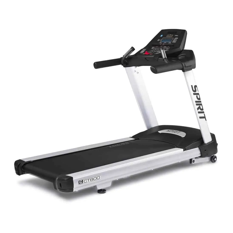
- Page 11 CONSOLE READING RACK CONSOLE FAN HEART RATE GRIPS BOTTLE HOLDER HANDLEBARS SAFETY KEY CONSOLE MAST SIDE RAILS MOTOR COVER RUNNING BELT/DECK TREAD-BELT TRACKING www.spiritfitness.com...
- Page 12 CT800 STEP ONE HARDWARE FOR STEP 1 PART TYPE DESCRIPTION BUTTON HEAD SOCKET BOLT 3/8” x 3” Ø10 x 2T SPLIT WASHER FLAT WASHER Ø3/8” x 35 x 2.0T PHILLIPS HEAD SCREWS M5 x 12mm 1. Gather Hardware for Step 1.
- Page 13 CT800 STEP TWO HARDWARE FOR STEP 2 PART TYPE DESCRIPTION SOCKET HEAD CAP BOLT M8 x 12mm Ø8 x Ø16 x 2T FLAT WASHER BUTTON HEAD SOCKET BOLT 3/8” x 3/4” SPLIT WASHER Ø10 x 2T FLAT WASHER Ø3/8” x Ø25 x 2.0T 1.
- Page 14 CT800 STEP THREE HARDWARE FOR STEP 3 PART TYPE DESCRIPTION BUTTON HEAD SOCKET 3/8” x UNC16 BOLT x1-1/4 SPLIT WASHER Ø10 x 2T CURVED WASHER Ø10 x Ø23 x 1.5T ROUND CAP 1. Gather Hardware For Step 3. 2. Further secure the uprights by inserting a Button Head Socket Bolt (No.154) through a Split...
- Page 15 CT800 STEP FOUR HARDWARE FOR STEP 4 PART TYPE DESCRIPTION SOCKET HEAD CAP BOLT M8 x P1.25 x 20L SPLIT WASHER Ø8 x 1.5T FLAT WASHER Ø8 x Ø16 x 2T M5 x 12mm PHILLIPS HEAD SCREW 1. Gather Hardware for Step 4.
-
Page 16: Console Operation
CT800 CONSOLE OPERATION Spirit Fitness... - Page 17 Dot Matrix Scan Button for Message Center LED Windows Direct Access LED Data Display Speed Buttons Windows Scan Button for Up, Down, Dot Matrix Program Controls Direct Access Incline Buttons Charger Water bottle holder and cargo compartment for buttons, phone, or MP3 player Contact Heart Start, Stop, Speed, and...
- Page 18 POWER Power the treadmill on by plugging it into an appropriate wall outlet, then turn on the power switch located at the front of the treadmill below the motor hood. Ensure that the safety button is installed, as the treadmill will not power on without it.
- Page 19 2. Fasten the plastic clip onto your clothing securely to assure good holding power. Note: The magnet has strong enough power to minimize accidental, unexpected stopping. The clip should be attached securely to make certain it does not come off. Be familiar with its function and limitations. The treadmill will stop, depending on speed, with a one to two step coast anytime the magnet is pulled off the console.
- Page 20 When you are setting data, such as age and time, for a program pressing the Stop button will allow you to go • back one step for each button press. INCLINE Incline may be adjusted anytime after the belt starts moving. •...
- Page 21 You must use both left and right stainless steel sensors to pick up your pulse. Pulse values are displayed anytime the computer is receiving a Grip Pulse signal. You may use the Grip Pulse feature while in Heart Rate Control. The CT800 will also pick up wireless heart rate transmitters that are Polar compatible, including coded transmissions.
-
Page 22: Programmable Features
TO SELECT AND START A PRESET PROGRAM The Spirit Fitness CT800 offers twelve preset programs, Hill, Fat Burn, Cardio, Interval, HIIT (High Intensity Interval Training), 5k Run, 10k Run, a Custom User defined program, two heart rate control programs, a Fitness Test (Gerkin, Army, Navy, Airforce, Marine Corps, Coast Guard, PEB), and one Manual program. - Page 23 PRESET PROGRAMS SPEED/INCLINE SETTINGS The preset program Speed and Incline levels are shown in the chart below. The Speed numbers shown in the chart indicate a percentage of the top speed of the program. For instance, the first Speed setting for P1 (Program 1, HILL) shows the number 20.
- Page 24 HILL This program follows a triangle or pyramid type of gradual progression from approximately 10% of maximum effort (the level that you chose before starting this program) up to a maximum effort which lasts for 10% of the total workout time, then a gradual regression of resistance back to approximately 10% of maximum effort FAT BURN...
- Page 25 INTERVAL This program takes you through high levels of intensity followed by recovery periods of low intensity. This program utilizes and develops your “Fast Twitch” muscle fibers which are used when performing tasks that are intense and short in duration. These deplete your oxygen level and spike your heart rate, followed by periods of recovery and heart rate drop to replenish oxygen.
- Page 26 then press Enter. The time for the Rest period will blink and you can adjust the time using the Up/Down keys and press Enter. The Dot Matrix Message Center now displays SPRINT SPD 6.0 MPH. Use the Up/Down buttons to adjust the sprint speed you desire and press Enter.
- Page 27 CUSTOM PROGRAM 1. Select the Custom program using the Program button then press Enter. Note that the Dot Matrix Message Center will light a single row of dots at the bottom (Unless there is a previously saved program). 2. The clock (Time) window will be flashing. Use the Up/Down buttons to set the program for the desired time. Press the Enter button.
- Page 28 FITNESS TEST When the Fit-Test button is pressed the dot matrix displays the 5 different tests available: Gerkin, Army, Navy, Air Force, Marines, PEB, Coast Guard. To select your desired fitness test use the arrow button and press enter. FITNESS TEST OPERATION 1.
- Page 29 3:45 5.0mph 46.2 4:00 5.0mph 46.5 4:15 5.5mph 48.6 GERKIN TEST 4:30 5.5mph 4:45 5.5mph 51.4 The Gerkin protocol, also known as the fireman’s protocol, and is a submax Vo2 (volume of oxygen) test. 5:00 5.5mph 52.8 The test will increase speed and elevation alternately until you reach 85% of your Max heart rate. The time 5:15 5.5mph 53.9...
- Page 30 ARMY AIR FORCE A timed 2 mile run. You control the speed manually. A timed 1.5 mile run. You control the speed manually. Maximum time allowed to pass the test: Maximum time allowed to pass the test: Male Female Male Female 17-21 16:36...
- Page 31 A timed 1.5 mile run. You control the speed manu- ally. Maximum time allowed to pass the test: Male Female Male Female 20-24 10:43 13:36 45-49 13:07 16:02 25-29 11:05 13:43 50-54 13:49 17:02 30-34 11:26 13:43 55-59 14:48 17:37 35-39 11:47 14:37...
- Page 32 Before The Test: Make sure you are in good health; check with your physician before performing any exercise if you are over the • age of 35 or persons with pre-existing health conditions. Make sure you have warmed up and stretched before taking the test. •...
- Page 33 poor 30-36 30-34 26-30 25-28 22-25 20-21 very poor <30 <30 <26 <25 <22 <20 WHAT YOUR SCORE MEANS Vo2max Chart For Males And Very Fit Females Vo2max Chart For Females And De-Conditioned Males 18-25 26-35 36-45 46-55 56-65 18-25 26-35 36-45 46-55...
-
Page 34: Heart Rate Programs
HEART RATE PROGRAMS The old motto, “no pain, no gain”, is a myth that has been overpowered by the benefits of exercising comfortably. A great deal of this success has been promoted by the use of heart rate monitors. With the proper use of a heart rate monitor, many people find that their usual choice of exercise intensity was either too high or too low and exercise is much more enjoyable by maintaining their heart rate in the desired benefit range. - Page 35 If you enter your age during programming the console will perform this calculation automatically. Entering your age is used for the Heart Rate programs. After calculating your MHR you can decide upon which goal you would like to pursue. The two most popular reasons for, or goals, of exercise are cardiovascular fitness (training for the heart and lungs) and weight control.
- Page 36 85% of your Maximum Heart Rate. Your Maximum Heart Rate is based upon a formula that subtracts your age from a constant of 220. Your HR setting is automatically calculated during the setup mode when you enter your age. HEART RATE CONTROL PROGRAMMING 1.
- Page 37 RATE OF PERCEIVED EXERTION There are more variables involved in how hard you should workout than just heart rate. Your stress level, physical health, emotional health, temperature, humidity, the time of day, the last time you ate and what you ate, all contribute to the intensity at which you should workout. The rate of perceived exertion (RPE), also know as the Borg scale, was developed by Swedish physiologist G.A.V.
- Page 38 WEARING THE CHEST STRAP (SOLD SEPARATELY) 1. Attach the transmitter to the elastic strap using the interlocking button. 2. Adjust the strap as tightly as possible while ensuring it is still comfortable. 3. Position the transmitter with the logo centered in the middle of your torso facing away from your chest (some people must position the transmitter slightly left of center).
- Page 39 ERRATIC OPERATION Caution! Do not use this treadmill for Heart Rate programs unless a steady, solid Actual Heart Rate value is being displayed. High, wild, random numbers being displayed indicate a problem. Areas to look for interference which may cause erratic heart rate: 1.
- Page 40 CALIBRATION PROCEDURE 1. Remove the safety key. 2. Press and hold down the Start and Speed Up buttons and replace the safety button. Continue to hold the Start and Speed Up button until the window displays “Factory settings”, then press the Enter button. 3.
- Page 41 BELT ADJUSTMENTS Tread-belt Tension Adjustment - Belt tension is not critical for most users. It is very important though for joggers and runners in order to provide a smooth, steady running surface. Adjustment must be made from the rear roller with the 8mm Allen wrench provided in the parts package.
- Page 42 TREADBELT TRACKING ADJUSTMENT The treadmill is designed so that the tread-belt remains reasonably centered while in use. It is normal for some belts to drift near one side while in use, depending on a user’s gait and if they favor one leg. But if during use the belt continues to move toward one side, adjustments are necessary.
- Page 43 ENGINEERING MODE MENU The console has built in maintenance/diagnostic software. The software will allow you to change the console settings from English to Metric and turn off the beeping of the speaker when a button is pressed for example. To enter the Engineering Mode Menu press and hold down the Start, Stop and Enter buttons, then insert the safety button.
- Page 44 TROUBLESHOOTING - DIAGNOSIS GUIDE PROBLEM SOLUTION/CAUSE Display does not light 1. Tether cord not in position. 2. Circuit breaker on front grill tripped. Push circuit breaker in until it locks. 3. Plug is disconnected. Make sure plug is firmly pushed into 110 - 120 VAC wall outlet.
- Page 45 Treadmill will only achieve approximately 7 mph but This indicates motor should be receiving power to oper- shows higher speed on display ate. Low AC voltage to treadmill. Do not use an extension cord. If an extension cord is required it should be as short as possible and heavy duty 16 gauge minimum.
-
Page 46: General Maintenance
GENERAL MAINTENANCE 1. After each workout, wipe down all areas exposed to sweat with a damp cloth. 2. Ensure all bolts are properly tightened after assembly and before each use. 3. Ensure that the unit is properly leveled after assembly and before each use. Use leveling pads on the bottom of the feet to adjust height. - Page 47 TREADMILL WARRANTY EFFECTIVE MARCH 18, 2020 Spirit Fitness warrants all its Treadmill parts for a period of time listed below from the date of retail sale, as determined by sale receipt, or in the absence of a sales receipt eighteen (18) months from the original factory shipping date.
- Page 48 EXCLUSIONS This warranty does not cover the following: 1. CONSEQUENTIAL, COLLATERAL, OR INCIDENTAL DAMAGES SUCH AS PROPERTY DAMAGE AND INCIDENTAL EXPENSES RESULTING FROM ANY BREACH OF THIS WRITTEN OR ANY IMPLIED WARRANTY. NOTE: Some states do not allow the exclusion or limitation of incidental or consequential damages, so this limitation or exclusion may not apply to you.
- Page 49 SERVICE Keep your bill of sale. Twelve (12) months from the date on the bill of sale or eighteen (18) months from the date of factory shipping as determined by the serial number establishes the labor warranty period should service be required. If service is performed, it is in your best interest to obtain and keep all receipts. This written warranty gives you specific legal rights.
- Page 50 NOTES Spirit Fitness...
- Page 51 NOTES www.spiritfitness.com...
- Page 52 Spirit Fitness...
- Page 53 CT800 - ST8600 - YT057 - 01 Part List SPIRIT (LED, 120V Rear Adjustment Base (R) Part Name Q'TY Console Assembly Main Frame Rack Top Cover Incline Bracket Rack Bottom Cover Locking Plate Assembly ( R ) Console Cover Locking Plate Assembly ( L)
- Page 54 Ø8.5 × Ø26 × 2.0T_Flat Washer Ø5 × 1.5T_Split Washer M10 × P1.5 × 65m/m_Hex Head Bolt M5 × 12m/m_Phillips Head Screw M10 × P1.5 × 50m/m_Hex Head Bolt M5 × 5T_Nylon Nut Ø10 × 1.5T_Split Washer M5_Star Washer Ø3/8" × Ø19 × 1.5T_Flat Washer 3.5 ×...
- Page 55 www.spiritfitness.com...
- Page 56 800.258.4555 Spirit Fitness spiritservice@spiritfitness.com 3000 Nestle Road www.spiritfitness.com Jonesboro, AR 72401 CT800 Owners Manual © 2020 All Rights Reserved Revision 2: 06.03.2020...
Need help?
Do you have a question about the CT800 and is the answer not in the manual?
Questions and answers