Table of Contents
Advertisement
Quick Links
Advertisement
Table of Contents

Related Manuals for DAN DRYER Loki


Summary of Contents for DAN DRYER Loki
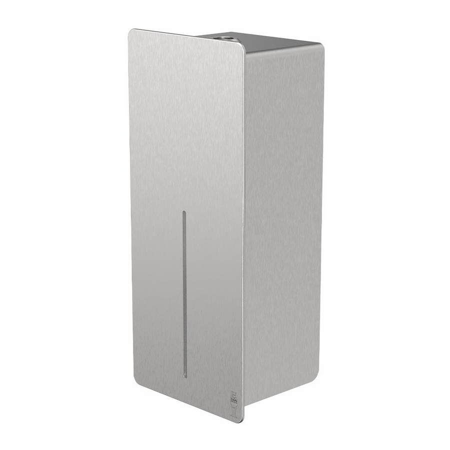
- Page 1 USER MANUAL LOKI HAND DRYER Model: 4000 - 4007...
-
Page 2: Table Of Contents
TABLE OF CONTENTS Dimensions and technical specifications General safety information Circuit diagram Installation User guide Recommended installation height Cleaning and maintenance Adjustment of warm air speed output Heating element switch Adjustment of sensor range Troubleshooting and corrective actions Symptoms and corrective actions of first-time installed hand dryers Symptoms and corrective actions of used hand dryers Parts list IMPORTANT! -
Page 3: Dimensions And Technical Specifications
PRODUCT TYPE / MODEL 4000 / 4001 Stainless steel, brushed, LOKI hand dryer, 230V/110V 4002 / 4003 White powder coated stainless steel, LOKI hand dryer, 230V/110V 4004 / 4005 Black powder coated stainless steel, LOKI hand dryer, 230V/110V 4006 / 4007 Custom RAL colour, stainless steel, LOKI hand dryer, 230V/110V... -
Page 4: General Safety Information
GENERAL SAFETY INFORMATION WARNING • All units must be equipped with a 3-wire service. Connect the ground wire according to the instructions. • This product must be installed only by qualified persons. Use 2.0mm (AWG) NO.14 wiring. • Turn off the power to the unit before servicing or cleaning. All wires must be disconnected. •... -
Page 5: Installation
INSTALLATION • Make sure the main breaker is turned off. Installation must be carried out by a qualified person in accordance with standards applicable in the country where the equipment is to be installed. • Place template against the wall at desired height (see mounting height recommendations) and mark location of (4) mounting holes and the wire service entry. -
Page 6: User Guide
USER GUIDE • No-touch operation. • Shake excess water from hands. • Place hands under the outlet to start operation. • Rub hands lightly and rapidly. • Stops automatically after hands are removed. RECOMMENDED INSTALLATION HEIGHT From bottom edge of hand dryer above finished floor. 1270 mm (50”) Women... -
Page 7: Adjustment Of Warm Air Speed Output
WARM AIR SPEED ADJUSTMENT • Switch off the power and remove the cover. • Use Phillips screwdriver or flat notch. The air speed is adjusted on the VR potentiometer. Clockwise to increase air speed(+). Counterclockwise to decrease air speed(-). HEATING ELEMENT SWITCH •... -
Page 8: Troubleshooting And Corrective Actions
TROUBLESHOOTING AND CORRECTIVE ACTIONS SYMPTOM CORRECTIVE ACTION: FIRST-TIME INSTALLED HAND DRYERS The dryer does not run First ensure that the breaker supplying the dryer is opera- tional. If it is, disconnect the power and remove the cover. Taking suitable precaution to avoid shock hazard, recon- nect the power and check for voltage on the terminal block. -
Page 9: Parts List
PARTS LIST No. Description Blower housing - upper Motor rubber - large Motor Motor brushes Motor rubber - small Blower housing - lower Heating element Air outlet Air outlet bracket Circuit Print Board Cable protector Bracket for IR sensor IR sensor Terminal block Insulation mylar shield with LNG mark... - Page 10 DAN DRYER A/S Alsikevej 8 DK - 8920 Randers NV T: +45 8641 5711 E: info@dandryer.dk W: dandryer.com...
Need help?
Do you have a question about the Loki and is the answer not in the manual?
Questions and answers