Table of Contents
Advertisement
Quick Links
Advertisement
Table of Contents

Subscribe to Our Youtube Channel
Summary of Contents for Dahua VTA2302A
- Page 1 Emergency Call Terminal (VTA2302A) Quick Start Guide V1.0.0...
-
Page 2: Foreword
Foreword General This manual introduces the installation, functions and operations of the Emergency Call Terminal (hereinafter referred to as "the Terminal"). Safety Instructions The following categorized signal words with defined meaning might appear in the manual. Signal Words Meaning Indicates a high potential hazard which, if not avoided, will result in death or serious injury. - Page 3 format) cannot be opened. All trademarks, registered trademarks and the company names in the manual are the properties of their respective owners. Please visit our website, contact the supplier or customer service if there is any problem occurring when using the device. If there is any uncertainty or controversy, we reserve the right of final explanation.
-
Page 4: Important Safeguards And Warnings
Important Safeguards and Warnings The chapter introduces the proper way of using the Terminal, and danger and property damage preventions. Before using the Terminal, read this manual carefully. Follow the instructions and keep this manual properly. Operating Requirements Do not place and install the Terminal in an area exposed to direct sunlight or near heat generating device. -
Page 5: Table Of Contents
Table of Contents Foreword ..............................I Important Safeguards and Warnings ....................III 1 Product Overview ..........................2 Introduction ..........................2 Structure ............................2 1.2.1 Front Panel ........................2 1.2.2 Rear Panel ........................3 1.2.3 Device Ports ........................4 Typical Networking ........................5 2 Installation ............................ -
Page 6: Product Overview
Product Overview Introduction The Terminal can be connected with the management platform and master station (VTS) to provide emergency calling, voice broadcasting, video monitoring, and more. It is applicable to schools, banks, industrial parks, apartments, office buildings and other places. And it can be configured on the web interface. -
Page 7: Rear Panel
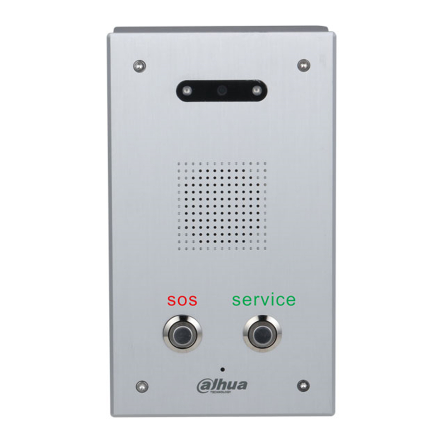
Table 1-1 Front panel description Name Description When the light is insufficient and the Terminal is monitored Illuminator or calling, the illuminator is turned on automatically. Speaker Outputs audio. Service button Calls the management center. Microphone Inputs audio. SOS button Sends alarms to the management center. -
Page 8: Device Ports
1.2.3 Device Ports Device ports Table 1-3 Device ports description Name Name Power input Alarm input 1 RS-485 Alarm input 2 Reserved ports Alarm output 1 Active speaker — — Alarm output 2... -
Page 9: Typical Networking
Typical Networking Networking The master station in the networking is optional. -
Page 10: Installation
Installation Do not install the Terminal in places with condensation, high temperature, grease, dust, chemical corrosion, or direct sunlight. In case of abnormality after powering on, cut off the power supply immediately, and then pull out the network cable. Power on again after troubleshooting. ... -
Page 11: Procedure
Mounting plate dimensions (mm [inch]) Procedure Drill 4 holes on the wall according to the screw holes on the mounting plate, and put the expansion bolts into the holes. Fix the mounting plate on the wall with the ST3×18 self-tapping screws. Apply sealant between the mounting plate and the wall, and to cover the cable outlets. - Page 12 Installation Table 2-2 Installation component Name Name M3X8 hexalobular socket screw Bottom cable outlet Emergency Call Terminal Rear cable outlet ST3×18 self-tapping screw Mounting plate...
-
Page 13: Web Operations
Web Operations Initialization For first-time login, or login after restoring to factory settings, you need to initialize the Terminal. The IP address is 192.168.1.108 by default. Make sure that the PC and the Terminal are in the same network segment. Enter the IP address of the Terminal in the address bar. -
Page 14: Login
Click OK. Initialization completed Login Enter the IP address of the Terminal in the address bar. Enter the username and password. Login interface Click Login. Password Reset If you forget the password when logging in to the web interface, you can reset the password. Click Forgot password? on the login interface. -
Page 15: Local Settings
Click Next, scan the QR code according to the on-screen prompts, and you will get the security code. In the Security Code box, enter the security code received in your provided mailbox. Enter the security code Click Next. Enter and confirm the new password. The password should consist of 8 to 32 non-blank characters and contain at least two types of characters among uppercase, lowercase, number, and special character (excluding ' "... -
Page 16: Video & Audio
Device name setting Click Confirm. 3.4.2 Video & Audio You can set the brightness, contrast, hue, saturation and scene mode of the monitoring screen, and adjust the volume of the Terminal. Select Local Setting > Video & Audio on the web interface. If the plug-in has not been installed, follow on-screen instructions to install it. - Page 17 Table 3-1 Video & audio parameter description Parameter Description The Terminal supports 720P (1280 × 720), WVGA (800 × 480), D1 Video Format (720 × 576), and CIF (352 × 288). You can select as needed. The number of frames per second in a video. The higher the frame Frame Rate rate is, the more clear and smooth the video will be.
-
Page 18: System Settings
Parameter Description high or low levels of light to maintain a normal and usable level of light for the object in focus. WDR: The system dims bright areas and compensates dark areas to ensure the clarity of all areas according to the lighting conditions. -
Page 19: Alarm Output Settings
Parameter Description Set NTP time synchronization. Select the NTP Enable check box. Configure parameters. NTP setting NTP Server: Enter the IP address of the time server for the Terminal to synchronize time. Port: Enter the port number of the time server. Interval: Enter the interval at which the time is synchronized. -
Page 20: Onvif User
Security management Table 3-4 Security management parameter description Parameter Description Enabled by default. The Terminal can connect with other network CGI Enable video products through this protocol. Onvif Enable CGI (Common Gateway Interface) is an interface between external programs and web server. Enabled by default to allow password resetting and setting reserved email address. -
Page 21: Network Settings
Add Onvif users Click Save. Network Settings 3.5.1 TCP/IP You can configure the IP address and DNS server to connect the Terminal to other devices in the network. Select Network > Basic on the web interface. Configure parameters. TCP/IP settings... -
Page 22: Firewall
Table 3-5 TCP/IP parameter description Parameter Description IP Address Enter the IP address, subnet mask, and default gateway you planned. Subnet Mask The IP address and default gateway must be in the same network Default Gateway segment. MAC Address The MAC (Media Access Control) address of the Terminal. Preferred DNS The IP address of the DNS server. - Page 23 Firewall When enabling PING Prohibited and Anti Half Connection, you do not need to set parameters. Click Confirm to complete the settings. When enabling Network Access, you need to configure white list or black list. Here are the steps. Select White List or Black List as the Mode.
-
Page 24: Register
Table 3-6 Firewall parameters description Parameter Description Select IP Address, IP Segment, MAC Address or All IP Addresses. IP Address: Select the IP version, and then enter the IP address to be added. IP Segment: Select the IP version, and then enter the Initial IPv4 Type Address, and End IPv4 Address. -
Page 25: Logout
Logout Click , and then select Exit to log out. Restart Click , and then select Reboot to restart the Terminal. Restoring to Factory Settings Click , and then select Factory Defaults to restore the Terminal to factory settings. The operation will clear the data of the Terminal. Be cautious. -
Page 26: Basic Functions
Basic Functions Calling If you have connected the Terminal to the entrance and exit management platform or master station, you can press the SOS or service button on the Terminal to call the platform client and master station. For details of adding the Terminal to the platform or master station, see the platform user's manual or the master station user's manual. -
Page 27: Faq
Table 5-1 FAQ Problem Solution The Terminal has no sound or light, Check whether the power supply is normal and the socket is in good and cannot be contact. powered on. There is a prompt Network failure. Check whether the network cable is properly that the call is not connected. -
Page 28: Cybersecurity Recommendations
Cybersecurity Recommendations Cybersecurity is more than just a buzzword: it’s something that pertains to every device that is connected to the internet. IP video surveillance is not immune to cyber risks, but taking basic steps toward protecting and strengthening networks and networked appliances will make them less susceptible to attacks. - Page 29 We suggest you to change default HTTP and other service ports into any set of numbers between 1024~65535, reducing the risk of outsiders being able to guess which ports you are using. Enable HTTPS We suggest you to enable HTTPS, so that you visit Web service through a secure communication channel.
- Page 30 suggested to use VLAN, network GAP and other technologies to partition the network, so as to achieve the network isolation effect. Establish the 802.1x access authentication system to reduce the risk of unauthorized access to private networks. It is recommended that you enable your device's firewall or blacklist and whitelist feature to reduce the risk that your device might be attacked.
Need help?
Do you have a question about the VTA2302A and is the answer not in the manual?
Questions and answers