Table of Contents
Advertisement
Advertisement
Table of Contents

Subscribe to Our Youtube Channel
Related Manuals for AMETEK/PRESTOLITE POWER AC1000 Control


Summary of Contents for AMETEK/PRESTOLITE POWER AC1000 Control
- Page 1 OWNER’S MANUAL 193111-055 Revised November 17, 2020 IMPORTANT: Read these instructions before installing, operating, or servicing this system. ACCU-CHARGER Silicon Diode Ferroresonant Transformer type Battery Charger DO NOT DESTROY AMETEK/PRESTOLITE POWER , TROY, OHIO 45373-1099, U.S.A.
- Page 3 NOTE: Information regarding obtaining additional copies of this manual is located in the Introduction chapter of this manual. A battery charger is identified by model number. Incorporated into the model number is the 8-hour ampere-hour capacity, case size, input power phase, and number of cells in battery for which charger is intended.
-
Page 5: Table Of Contents
193111-055 TABLE OF CONTENTS INTRODUCTION ..........................How to use this Manual ..................... 1-1 Equipment Identification ....................1-1 Receipt of Equipment ......................1-1 SAFETY INSTRUCTIONS AND WARNINGS ............... 2 DESCRIPTION OF EQUIPMENT ....................INSTALLATION ............................ Location ..........................4-1 Environmental Characteristics ................... 4-1 Grounding ......................... - Page 6 193111-055 TABLE OF CONTENTS This page intentionally left blank. November 17, 2020...
-
Page 7: Introduction
193111-055 INTRODUCTION INTRODUCTION How To Use This Manual NOTE offers helpful information concerning certain operating procedures. Notes will be shown in italics. Equipment Identification The unit's identification number (specification, model, IMPORTANT: It is especially serial number) usually appears on a nameplate important that all charger attached to the front panel. - Page 8 193111-055 INTRODUCTION This page intentionally left blank. November 17, 2020...
-
Page 9: Safety Instructions And Warnings
193111-055 SAFETY INSTRUCTIONS AND WARNINGS SAFETY INSTRUCTIONS AND WARNINGS FOR OPERATION OF BATTERY Equipment – Electrical equipment must be installed and maintained in accordance with the National CHARGING EQUIPMENT Electrical Code, NFPA 70, and local codes. A power disconnect switch must be located at the equipment. - Page 10 193111-055 SAFETY INSTRUCTIONS AND WARNINGS C. Burn and Bodily Injury Prevention The battery produces very high currents when short circuited, and will burn the skin severely if in contact DANGER: ELECTRICAL SHOCK with any metal conductor that is carrying this current. Do not permit rings on fingers to come in contact with CAN BE FATAL.
-
Page 11: Description Of Equipment
DESCRIPTION OF EQUIPMENT DESCRIPTION OF EQUIPMENT Charger The AC1000 Control is “matched” to the output voltage of the charger by means of a printed circuit board The basic charging circuit is the silicon diode, mounted DIP switch. It will operate on 6, 12, 18, 24, rectifier-type with ferroresonant transformer (s). - Page 12 193111-055 DESCRIPTION OF EQUIPMENT This page intentionally left blank. November 17, 2020...
-
Page 13: Installation
193111-055 INSTALLATION INSTALLATION Location electrical charges which tend to build up on the surfaces of equipment. These static charges can For best operating characteristics and longest unit life, cause painful shock to personnel, and can lead to the take care in selecting an installation site. Avoid erroneous conclusion that an electrical fault exists in locations exposed to high humidity, dust, high ambient the equipment. -
Page 14: Line Voltage Changeover Instructions
193111-055 INSTALLATION DISCONNECT BRANCH FUSE COPPER CABLE SIZE AWG * * LINE SWITCH * SIZE (AMPERES) AMPS POWER GROUND 0-2.5 No. 14 No. 14 2.6-4.5 No. 14 No. 14 4.6-7.5 No. 14 No. 14 7.6-12 No. 14 No. 14 12.1-16 No. -
Page 15: Charging Cable Connectors
193111-055 INSTALLATION 4. Route AC power input cable in through knock-out Pre-operation Checks provided in side panel of charger cabinet. Securely fasten cable wires to a power input terminal inside charger. Refer to Grounding section of this manual 1. Inspect charger thoroughly for damage; loose for proper connection of grounding conductor. -
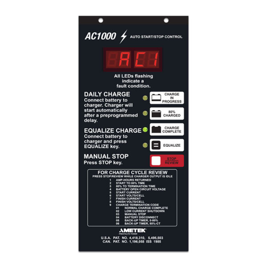
Page 16: Operation
193111-055 OPERATION OPERATION Preliminary STOP key, then disconnect the battery from the charger. 1. Make sure that charger is installed and grounded as Equalize or Weekend Charge instructed in this manual. 2. Make sure the charge control is set to the proper The AC1000 features Auto Equalize every 5th charge cell size via the charge control DIP switch cell cycle and is shipped with auto equalize feature ena-... -
Page 17: Manual Stop
10 hours of charging. 2. To restart the charger, disconnect and reconnect the Likewise, if the AC1000 Control is set to terminate via battery. A new charge cycle will begin. the pT/dV/dT methodology (DIP switch S1-2 set to... -
Page 18: Battery Disconnect Shutdown
Battery Disconnect Shutdown AC POWER FAIL If the battery is disconnected from the charger during a During an AC power failure, the AC1000 Control stores charge cycle, the charger will be shutdown. All LEDs key information about the charge cycle. The infor- will be off. - Page 19 193111-055 OPERATION Figure 5-1 November 17, 2020...
-
Page 20: Maintenance
193111-055 MAINTENANCE MAINTENANCE Lubrication WARNING: ELECTRICAL SHOCK HAZARD — Before inspecting or None required. cleaning inside cabinet, turn OFF and remove fuses of disconnect Charging Rate Adjustment switch (supplying AC power to charger), disconnect battery, and Although it is normally not required, the charging rate check for voltage on capacitors. -
Page 21: Fuse Replacement
193111-055 MAINTENANCE Table 6-1 Charging Rate Adjustment Table 1. Locate charging rate adjustment label inside charger Fuse Replacement cabinet (same as Table 6-1). The factory set charging rate is indicated on this label by circles The silicon diodes in this charger are protected by a around terminal numbers to which YELLOW jumper “fast-clearing”... -
Page 22: Capacitor Testing
193111-055 MAINTENANCE 6. Consider diode good if one resistance reading is 3. If capacitor is good, pointer will deflect, indicating infinitely (or very) high and the other is extremely capacitor is being charged, followed by a deflection low. in the opposite direction indicating partial discharge. NOTE: An acceptable low resistance value If there is no deflection, capacitor is “open”... -
Page 23: Troubleshooting
193111-055 MAINTENANCE Troubleshooting DANGER: ELECTRICAL SHOCK HAZARD — Before checking electrical components, turn OFF and remove fuses of disconnect switch (supplying AC power to charger), disconnect battery, and check for voltage on capacitors. Discharge through insulated screwdriver if there is any reading. CAUTION: HIGH VOLTAGE FROM TEST EQUIPMENT can damage silicon diodes and other parts. - Page 24 193111-055 MAINTENANCE Replace capacitor if can is ruptured or fails test. Refer to Capacitor Testing in Maintenance chapter. Check charging rate for "too low" adjustment. Refer to Charging Rate Adjustment in Maintenance chapter. Check line voltage for connection to proper input voltage. Refer to Line Voltage Changeover instructions in Installation chapter.
- Page 25 193111-055 MAINTENANCE DANGER: ELECTRICAL SHOCK HAZARD — Before checking electrical components, turn OFF and remove fuses of disconnect switch (supply AC power to charger), disconnect battery, and check for voltage on capacitors. Discharge through insulated screwdriver if there is any reading. November 17, 2020...
- Page 26 193111-055 MAINTENANCE DANGER: ELECTRICAL SHOCK HAZARD — Before checking electrical components, turn OFF and remove fuses of disconnect switch (supply AC power to charger), disconnect battery, and check for voltage on capacitors. Discharge through insulated screwdriver if there is any reading. November 17, 2020...
- Page 27 193111-055 MAINTENANCE DANGER: ELECTRICAL SHOCK HAZARD — Before checking electrical components, turn OFF and remove fuses of disconnect switch (supply AC power to charger), disconnect battery, and check for voltage on capacitors. Discharge through insulated screwdriver if there is any reading. November 17, 2020...
-
Page 28: Options
193111-055 OPTIONS OPTIONS The options listed in the following table of contents are those most commonly available. Special options not listed here will be covered by enclosed “addendum” sheets. OPTION NUMBER OPTION DESCRIPTION PAGE Parallel Charging..……………………………………….….7-1 Series Charging……………………………………...……...7-1 Remote Charge Control and Ammeter……….…..……..7-2 Fused Disconnect Switch and 24V Control Circuit…...7-2 Parallel Charging –... -
Page 29: Remote Charge Control - Option 101
193111-055 OPTIONS For series charging, both batteries must be at identical Option 500 (Refer to Figure 7-3) depths of discharge (DOD); ie, they are used in series in the vehicle. A mismatch in DOD of the two batteries This option is provided to meet certain “JIC” require- will result in severe overcharge of the lightly ments. -
Page 30: Parts List
193111-055 PARTS LIST Figure 8-1 “A” Case November 17, 2020... - Page 31 193111-055 PARTS LIST “A” CASE PARTS LIST ITEM NO. PART NO. DESCRIPTION 197157 Panel, Rear 197159 Panel, Side, Right 197158 Panel, Side, Left 197163 197164 Door 197165 Hinge 197324 Base 357205-357 Lead, Yellow (1 Req'd) 357205-127 Lead, Orange (1 Req'd) 357205-128 Lead, White (1 Req'd) 357205-060...
- Page 32 193111-055 PARTS LIST Figure 8-2 “B” Case November 17, 2020...
- Page 33 193111-055 PARTS LIST “B” CASE PARTS LIST Item No. Part No. Description 194457 Panel, Top 405548 Label, Frame Ground Table 8-3 Block, Fuse, Input Table 8-3 Fuse, Input Table 8-3 Contactor, Line Table 8-4 Transformer, Control 400092 Label, L1 400096 Label, L2 194827-1 Grommet, Mounting...
- Page 34 193111-055 PARTS LIST Figure 8-3 “C” Case November 17, 2020...
- Page 35 193111-055 PARTS LIST “C” CASE PARTS LIST Item No Part No. Description 405548 Label, Frame Ground Table 8-3 Block, Fuse, Input Table 8-3 Fuse, Input 194376 Panel, Top Table 8-3 Contactor, Line Table 8-4 Transformer, Control 400092 Label, L1 400096 Label, L2 400097 Label, L3...
- Page 36 193111-055 PARTS LIST Note 1: Item 15 (Rear Panel), for chargers with weather-resistant enclosure (Opt. 013), is 196546. Note 2: Item 37 (Left Side Panel), for chargers with weather-resistant enclosure (Opt. 013), is 1965561. DIODE PART NUMBER NO. CELLS 3-Phase 3-Phase from Charger having...
- Page 37 193111-055 PARTS LIST November 17, 2020...
- Page 38 193111-055 PARTS LIST Disconnect Disconnect Door Latch Label, Disc. Sw. “B” Case “C” Case Switch Switch (for Disc. Sw.) Part No. Right Side Panel Right Side Panel (Option 500) Part No. Part No. Part No. Part No. Without Disc. Sw. None None None...
-
Page 39: Diagrams
193111-055 DIAGRAMS DIAGRAMS Model no. Information DIAGRAM OUTLINE OUTPUT SCHEMATIC DIMENSION CASE SIZE LAST 2 DIGITS — 197325 197203 — 396513 194449 — 396520 194449 — 196612 194449 — 193536 194449 See model number description inside front cover. November 17, 2020...
Need help?
Do you have a question about the AC1000 Control and is the answer not in the manual?
Questions and answers