Table of Contents
Advertisement
Quick Links
OWNER'S MANUAL 193111-079
Issued March 7, 2008
IMPORTANT: Read these instructions before installing, operating, or
servicing this system.
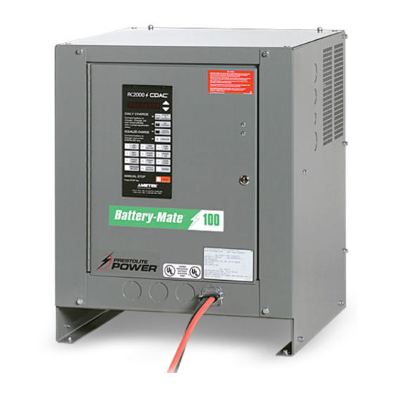
BATTERY-MATE 100
CHARGERS
Silicon Diode Ferroresonant
Transformer Type
DO NOT DESTROY
Note: This manual also applies to ST-100 units that were shipped prior to
January 1, 2005.
AMETEK/PRESTOLITE POWER , TROY, OHIO 45373-1099, U.S.A.
Advertisement
Table of Contents

Related Manuals for AMETEK/PRESTOLITE POWER BATTERY-MATE 100


Summary of Contents for AMETEK/PRESTOLITE POWER BATTERY-MATE 100
- Page 1 IMPORTANT: Read these instructions before installing, operating, or servicing this system. BATTERY-MATE 100 CHARGERS Silicon Diode Ferroresonant Transformer Type DO NOT DESTROY Note: This manual also applies to ST-100 units that were shipped prior to January 1, 2005. AMETEK/PRESTOLITE POWER , TROY, OHIO 45373-1099, U.S.A.
- Page 2 NOTE: Information regarding obtaining additional copies of this manual is located in the Introduction chapter of this manual. A battery charger is identified by model number. Incorporated into the model number is the 8-hour ampere-hour capacity, case size, input power phase, and number of cells in battery for which charger is intended.
-
Page 3: Table Of Contents
193111-079 TABLE OF CONTENTS INTRODUCTION ............................1 How to use this Manual ........................1-1 Equipment Identification ........................1-1 Receipt of Equipment .........................1-1 SAFETY INSTRUCTIONS AND WARNINGS.................... 2 DESCRIPTION OF EQUIPMENT....................... 3 INSTALLATION ............................4 Location ..............................4-1 Environmental Characteristics......................4-1 Grounding............................4-1 Line Voltage Changeover Instructions ....................4-2 Line Connections to Battery Charger ....................4-2 Charging Cable Connectors .......................4-3 Pre-operation Checks.........................4-3... -
Page 4: Introduction
193111-079 INTRODUCTION INTRODUCTION How To Use This Manual NOTE offers helpful information concerning certain operating procedures. Notes will be shown in italics. IMPORTANT: It is especially Equipment Identification important that all charger The unit's identification number (specification, model, internal components be kept serial number) usually appears on a nameplate clean and dry, and all attached to the front panel. -
Page 5: Safety Instructions And Warnings
193111-079 SAFETY INSTRUCTIONS AND WARNINGS SAFETY INSTRUCTIONS AND WARNINGS 1. Installation and Grounding of Electrically Powered FOR OPERATION OF BATTERY Equipment – Electrical equipment must be installed CHARGING EQUIPMENT and maintained in accordance with the National Electrical Code, NFPA 70, and local codes. A power disconnect switch must be located at the equipment. - Page 6 193111-079 SAFETY INSTRUCTIONS AND WARNINGS C. Burn and Bodily Injury Prevention DANGER: ELECTRICAL SHOCK The battery produces very high currents when short circuited, and will burn the skin severely if in contact CAN BE FATAL. If person is with any metal conductor that is carrying this current. unconscious and electric shock Do not permit rings on fingers to come in contact with is suspected, do not touch...
-
Page 7: Description Of Equipment
193111-079 DESCRIPTION OF EQUIPMENT DESCRIPTION OF EQUIPMENT Charger The AC500 Control is “matched” to the output voltage of the charger by means of a printed circuit board mounted DIP switch. It will operate on 6, 12, 18, 24, The basic charging circuit is the silicon diode, rectifier- 36, and “optional”... -
Page 8: Installation
193111-079 INSTALLATION INSTALLATION In addition to the usual function of protecting personnel Location against the hazard of electrical shock due to fault in the For best operating characteristics and longest unit life, equipment, grounding serves to discharge the static take care in selecting an installation site. Avoid electrical charges which tend to build up on the locations exposed to high humidity, dust, high ambient surfaces of equipment. -
Page 9: Line Voltage Changeover Instructions
193111-079 INSTALLATION DISCONNECT BRANCH FUSE SIZE COPPER CABLE SIZE AWG * * LINE AMPS SWITCH * (AMPERES) POWER GROUND 0-2.5 No. 14 No. 14 2.6-4.5 No. 14 No. 14 4.6-7.5 No. 14 No. 14 7.6-12 No. 14 No. 14 12.1-16 No. -
Page 10: Charging Cable Connectors
193111-079 INSTALLATION 4. Route AC power input cable in through knock-out Pre-operation Checks provided in side panel of charger cabinet. Securely fasten cable wires to a power input terminal inside 1. Inspect charger thoroughly for damage; loose charger. Refer to Grounding section of this manual screws, nuts, or electrical connections. -
Page 11: Operation
193111-079 OPERATION OPERATION Preliminary NOTE: To disconnect battery from charger before charge is complete, first press the STOP key, then disconnect the battery 1. Make sure that charger is installed and grounded as from the charger. instructed in this manual. Equalize or Weekend Charge 2. -
Page 12: Manual Stop
193111-079 OPERATION Refresh Charge WARNING: DO NOT connect a battery to this charger if any LED is lit. Do not In order to guarantee that a fully charged battery is disconnect a battery from this charger always ready for use, a “Refresh” feature has been while a charge is in progress;... -
Page 13: Battery Disconnect Shutdown
193111-079 OPERATION Battery Disconnect Shutdown AC POWER FAIL If the battery is disconnected from the charger during a During an AC power failure, the AC500 Control stores charge cycle, the charger will be shutdown. All LEDs key information about the charge cycle. The informa- will be off. -
Page 14: Maintenance
193111-079 MAINTENANCE MAINTENANCE Lubrication WARNING: ELECTRICAL SHOCK HAZARD — Before inspecting or None required. cleaning inside cabinet, turn OFF and remove fuses of disconnect Charging Rate Adjustment switch (supplying AC power to charger), disconnect battery, and Although it is normally not required, the charging rate check for voltage on capacitors. -
Page 15: Fuse Replacement
193111-079 MAINTENANCE Table 6-1 Charging Rate Adjustment Table 1. Locate charging rate adjustment label inside charger Fuse Replacement cabinet (same as Table 6-1). The factory set charging rate is indicated on this label by circles The silicon diodes in this charger are protected by a around terminal numbers to which YELLOW jumper “fast-clearing”... -
Page 16: Capacitor Testing
193111-079 MAINTENANCE 5. Reverse ohmmeter leads on diode and record 3. If capacitor is good, pointer will deflect, indicating indicated resistance. capacitor is being charged, followed by a deflection in the opposite direction indicating partial discharge. 6. Consider diode good if one resistance reading is infinitely (or very) high and the other is extremely If there is no deflection, capacitor is “open”... -
Page 17: Troubleshooting
193111-079 MAINTENANCE Troubleshooting DANGER: ELECTRICAL SHOCK HAZARD — Before checking electrical components, turn OFF and remove fuses of disconnect switch (supplying AC power to charger), disconnect battery, and check for voltage on capacitors. Discharge through insulated screwdriver if there is any reading. CAUTION: HIGH VOLTAGE FROM TEST EQUIPMENT can damage silicon diodes and other parts. - Page 18 193111-079 MAINTENANCE Low charging current at beginning of cycle (battery fully discharged) Check for failed capacitor (s) (one or more). Replace capacitor if can is ruptured or fails test. Refer to Capacitor Testing in Maintenance chapter. Check charging rate for "too low" adjustment. Refer to Charging Rate Adjustment in Maintenance chapter.
- Page 19 193111-079 MAINTENANCE DANGER: ELECTRICAL SHOCK HAZARD — Before checking electrical components, turn OFF and remove fuses of disconnect switch (supply AC power to charger), disconnect battery, and check for voltage on capacitors. Discharge through insulated screwdriver if there is any reading. March 7, 2008...
- Page 20 193111-079 MAINTENANCE DANGER: ELECTRICAL SHOCK HAZARD — Before checking electrical components, turn OFF and remove fuses of disconnect switch (supply AC power to charger), disconnect battery, and check for voltage on capacitors. Discharge through insulated screwdriver if there is any reading. March 7, 2008...
- Page 21 193111-079 MAINTENANCE DANGER: ELECTRICAL SHOCK HAZARD — Before checking electrical components, turn OFF and remove fuses of disconnect switch (supply AC power to charger), disconnect battery, and check for voltage on capacitors. Discharge through insulated screwdriver if there is any reading. March 7, 2008...
-
Page 22: Options
193111-079 OPTIONS OPTIONS The options listed in the following table of contents are those most commonly available. Special options not listed here will be covered by enclosed “addendum” sheets. OPTION NUMBER OPTION DESCRIPTION PAGE Parallel Charging..……………………………………….….7-1 Series Charging……………………………………...……...7-1 Remote Charge Control and Ammeter……….…..……..7-2 Fused Disconnect Switch and 24V Control Circuit…...7-2 Parallel Charging –... -
Page 23: Remote Charge Control - Option 101
193111-079 OPTIONS For series charging, both batteries must be at identical Fused Disconnect Switch – depths of discharge (DOD); ie, they are used in series Option 500 (Refer to Figure 7-3) in the vehicle. A mismatch in DOD of the two batteries will result in severe overcharge of the lightly discharged This option is provided to meet certain “JIC”... -
Page 24: Parts List
193111-079 PARTS LIST Figure 8-1 3 Phase March 7, 2008... - Page 25 405026 Label, Fuse, DC Output 194377 Hinge, Door 194458 Door, Hinged 193101-1 Rivet, Snap (2 Req’d.) Call Factory Control, Charger 196036 Label, Prestolite Power 404079 Label, UL and CUL 196665 Label, Charger, Battery-Mate 100 194530 Latch, Door March 7, 2008...
- Page 26 193111-079 PARTS LIST March 7, 2008...
- Page 27 193111-079 PARTS LIST March 7, 2008...
- Page 28 193111-079 PARTS LIST Figure 8-2 1 Phase March 7, 2008...
- Page 29 193111-079 PARTS LIST ITEM NO. PART NO. DESCRIPTION 197157 Panel, Rear 197159 Panel, Side, Right 197158 Panel, Side, Left 197163 197164 Door 197165 Hinge 197324 Base 357205-357 Lead, Yellow (1 Req'd) 357205-127 Lead, Orange (1 Req'd) 357205-128 Lead, White (1 Req'd) 357205-060 Jumper, Orange (2 Req'd) 357205-061...
- Page 30 193111-079 PARTS LIST March 7, 2008...
- Page 31 193111-079 PARTS LIST March 7, 2008...
- Page 32 193111-079 PARTS LIST March 7, 2008...
- Page 33 193111-079 DIAGRAMS DIAGRAMS MODEL NO. DIAGRAM DIAGRAM DIAGRAM OUTLINE INFORMATION 208/240/480V 480/575V 120/208/240V DIMENSION 3 PHASE 192120 192954 194449 (2 TRANSFORMERS) 1 PHASE 197325 197326 197325 197203 (1 TRANSFORMER) See model number description inside front cover. March 7, 2008...
- Page 40 AMETEK/PRESTOLITE POWER “FERRORESONANT” INDUSTRIAL BATTERY CHARGERS Ametek/Prestolite Power (hereinafter called “Prestolite”) warrants that each new and unused Industrial Battery Charger manufactured and supplied by it is of good workmanship and is free from any inherent mechanical defects, provided that (1) the product is installed and...
Need help?
Do you have a question about the BATTERY-MATE 100 and is the answer not in the manual?
Questions and answers