
Related Manuals for nilan Combi 302 Polar


Summary of Contents for nilan Combi 302 Polar
- Page 1 Installation instruction CTS 602 by Nilan Combi 302 Polar Version: 10.00, 28-11-2016...
-
Page 2: Table Of Contents
Accessories / spare parts ......................24 Figure table Figure 1: CTS 602 control ....................... 4 Figure 2: Mounting the Combi 302 Polar ..................5 Figure 3: Condensation drain / water seal..................6 Figure 4: Insulation of ducting ......................7 Figure 5: CTS 602 control ....................... 8 Figure 6: Headlines in the service menu .................. -
Page 3: Introduction
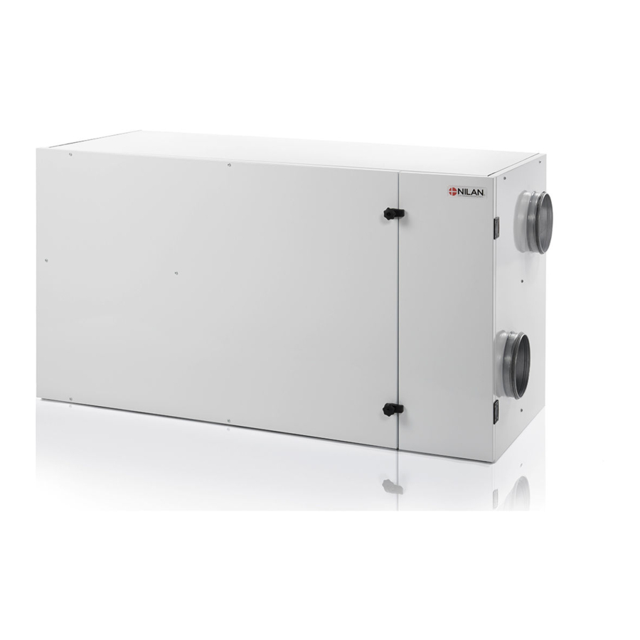
Combi 302 Polar is a combined passive and active heat recovery plant with a cooling function. The standard delivery of the Combi 302 Polar is with filter classes F5 (EU5) in the exhaust device and F7 (EU7) in the injection. -
Page 4: Power Supply
Power supply including safety switch must be installed by an authorized electrician. The Combi 302 Polar unit must be connected according to the attached electrical chart. The unit is delivered with 1m test cable for the CTS 602 panel. The panel should be connected to the CTS 602 control in the unit with cable type 2x2x0.25mm... -
Page 5: Assembly Of Combi 302 Polar
Assembly of Combi 302 Polar When mounting the Combi 302 Polar future service and maintenance should be consid- ered. It is recommended to have minimum 60 and 30 cm free space in front of- and at the end of the plant. -
Page 6: Condensation Drain / Water Seal
Condensation drain / water seal The Combi 302 Polar unit is delivered with a 20mm condensation drain. (PVC, GF-fittings). The drain is placed under the discharge. The condensation drain should be carried with an even inclination of at least 1 cm per meter, frost-proof to the nearest outlet. -
Page 7: Ducting
Ducting We recommend that there are used ducts and fittings with rubber packing that meet sealing class B and that the connections between the unit and the ducting are made with 1 metre sound absorb- ing flexible transitions as regards sound reduction. The ducts should be shortened with a hacksaw or an angle grinder and laid out according to the working drawing. -
Page 8: Starting And Set Up Of The Cts 602 Control
In this passage we will go through the service menu of the CTS 602 control. For daily use of the CTS 602 control please see the CTS 602 directions. (delivered together with the Combi 302 Polar). Use of t he CTS 600 panel : - pr ess ESC t o go one st ep back i n t he m enu - pr ess pt o m ove up or down i n a m enu or t o... -
Page 9: Activating The Service Menu
Activating the SERVICE menu Press and hold and ENTER simultaneously for 10 seconds. The SERVICE menu can then be accessed. Press repeatedly until SERVICE appears on the display. Press ENTER to activate the SERVICE menu. It is then possible to scroll through the SERVICE menu options using the p buttons. -
Page 10: Inlet Heating
Inlet heating In the ”Inlet heating” menu it is possible to activate and de-activate the heating surface in the inlet air and to set the regulation time. On the CTS602 control panel, press: - ESC to return to the previous menu - p to scroll upwards or downwards through the menus or to adjust the setting of an activated menu option - ENTER to activate a menu option... -
Page 11: Heating Surface
Heating surface The unit can be equipped with a heating surface. It is possible to retrofit a heating surface. The surface must be activated in the CTS 602 control in order to function together with the unit and for the frost-protection to be active. When installing a heating surface T7 is the temperature sensor in the inlet. -
Page 12: Air Quality
Air quality In the ”Air quality” menu it is possible to choose between 3 types of regulation: Humidity, Humidity + CO or OFF. On the CTS602 control panel, press: - ESC to return to the previous menu - p to scroll upwards or downwards through the menus or to adjust the setting of an activated menu option - ENTER to activate a menu option - ENTER to confirm a menu option setting... -
Page 13: Air Exchange
Air exchange The AIR EXCHANGE menu allows four ventilation steps (air quantities) to be set. Individual values for inlet and exhaust can be set for each ventilation step. A minimum ventilation step for inlet air and minimum and maximum steps for exhaust air can also be set. -
Page 14: Defrost
Defrost The DEFROST menu determines the mode of system operation while the evaporator surface and the counter flow heat exchanger in the exhaust air flow is being defrosted. Options that flash are indicated by ” ” On the CTS602 control panel, press: - ESC to return to the previous menu - p to scroll upwards or downwards through the menus or to adjust the setting of an activated menu option... -
Page 15: Temp. Control
Temp. control The temperature sensor to be used to control the system is selected in the TEMP. CONTROL menu. It is also possible to stipulate a minimum temperature at which the system is to be stopped to prevent further cooling of the building if the primary heating system has cut out for some reason. Options that flash are indicated by ”... -
Page 16: Inlet Control
Inlet control The inlet control menu makes it possible to set the time in which the compressor has to be shut off before restart. Parameters in the INLET CONTROL menu should only be set by experienced control technicians. On the CTS602 control panel, press: - ESC to return to the previous menu - p to scroll upwards or downwards through the menus or to adjust the setting of an activated menu option... -
Page 17: Room Control
Room control The ROOM CONTROL menu allows the room temperature controller to be set. Options that flash are indicated by ” ” Parameters in the ROOM CONTROL menu should only be set by experienced control technicians. On the CTS602 control panel, press: - ESC to return to the previous menu - p to scroll upwards or downwards through the menus or to adjust the setting of an activated menu option... -
Page 18: Restart
Restart The RESTART menu allows the system to be set to restart automatically in connection with high or low pressure faults. Fire alarms can be acknowledged automatically in connection with fire drills/testing. A condition for acknowledgement is that the fire thermostat input has returned to normal state. Options that flash are indicated by ”... -
Page 19: Preset
Preset The PRESET menu allows default factory settings to be stored. RESTORE menu allows you to reload a copy of the installation setup. By keeping the ESC + key pressed for 5 seconds a new menu item RESTORE appear, this is then acceptable / activated by pressing the ENTER Options that flash are indicated by ”... -
Page 20: Manual
Manual The MANUAL menu allows system functions to be tested manually. Options that flash are indicated by ” ” On the CTS602 control panel, press: - ESC to return to the previous menu - p to scroll upwards or downwards through the menus or to adjust the setting of an activated menu option - ENTER to activate a menu option - ENTER to confirm a menu option setting... -
Page 21: Modbus
Modbus Options that flash are indicated by ” ” On the CTS602 control panel, press: - ESC to return to the previous menu - p to scroll upwards or downwards through the menus or to adjust the setting of an activated menu option - ENTER to activate a menu option - ENTER to confirm a menu option setting - OFF switch off the controls... -
Page 22: Datalog
Datalog The datalog interval is set via the menu SERVICE - DATALOG INTV at between 1 and 120 minutes. If 0 / OFF is selected, logging is not periodical, but only on events and alarms. • Temperatures are logged in Celsius, in whole degrees, in order to minimise the log file size. •... -
Page 23: System Dimension
System dimension Combi 302 Polar 1 : Aussenluft 2 : Zuluft 3 : Abluft 4 : Fortluft 10 : Stromversorgung 11 : Kondens Ablauf Figure 20: System dimension This document may be subject to change Side 23 of 24... -
Page 24: Accessories / Spare Parts
Accessories / spare parts Combi 302 Polar Filter types Qty. Nilan item no. Filter sheet G4, 8 pcs. 391713 Filter cassette F7 39520 This document may be subject to change Side 24 of 24...
Need help?
Do you have a question about the Combi 302 Polar and is the answer not in the manual?
Questions and answers