Ariens Sno-Thro Compact Series Service Manual
Hide thumbs
Also See for Sno-Thro Compact Series:
- Operator's manual (36 pages) ,
- Operator's manual (36 pages) ,
- Operator's manual (34 pages)
Table of Contents
Advertisement
Service Guide
®
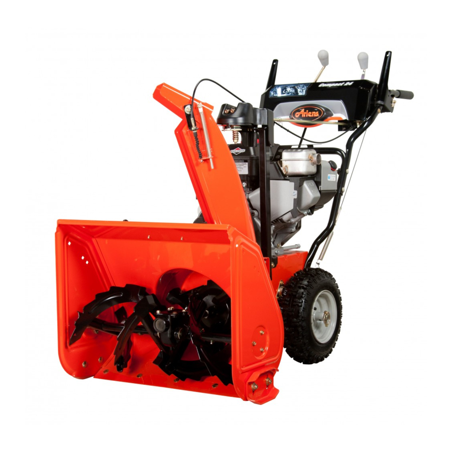
Compact Series Sno-Thro
Models
920025 – Compact Classic 24
(SN 000101 +)
920026 – Compact 20
(SN 000101 +)
920027 – Compact 24
(SN 000101 +)
920028 – Compact 24 Track
(SN 000101 +)
920317 – Compact 22 CE
(SN 250000 +)
920318 – Compact 24 Track CE
(SN 250000 +)
920321 – Compact 24 CE
(SN 250000 +)
920328 – Compact Classic 24 CE
(SN 000101 +)
E10
ENGLISH
05135330A • 7/18
Advertisement
Table of Contents

Related Manuals for Ariens Sno-Thro Compact Series


Summary of Contents for Ariens Sno-Thro Compact Series
- Page 1 Service Guide ® Compact Series Sno-Thro Models 920025 – Compact Classic 24 (SN 000101 +) 920026 – Compact 20 (SN 000101 +) 920027 – Compact 24 (SN 000101 +) 920028 – Compact 24 Track (SN 000101 +) 920317 – Compact 22 CE (SN 250000 +) 920318 –...
-
Page 2: Table Of Contents
TABLE OF CONTENTS PRACTICES & LAWS..... . 2 AUGER REPLACEMENT ....25 Remove Auger . - Page 3 AXLE BEARING REPLACEMENT (TRACK MODELS) ..... . . 49 Remove Right Bearing ......49 Install Right Bearing .
- Page 5 Installing unauthorized parts will not automatically void the warranty; however, the warranty will not apply if the installation and use of unauthorized parts damages the unit. The Ariens warranty applies solely to defects in Ariens materials and / or factory workmanship. Ariens disclaims liability for any claims or damages –...
-
Page 6: Practices & Laws
Failure to follow these instructions and warnings may cause death or serious 4. Notice injury. If you have purchased this product from an Ariens NOTICE: Indicates information or procedures that are dealer, the dealer can provide you with training. -
Page 7: Safety Decals
SAFETY DECALS Stop engine, remove key, and read manual The safety decals on your machine are visual reminders of before making any repairs or adjustments. the important safety information in this manual. All messages on your unit must be fully understood and carefully followed. -
Page 8: Safety Rules
SAFETY RULES Handle fuel with care; it is highly flammable. • Use an approved fuel container. The following safety instructions are based on the B71.3 specifications of the American National Standards Institute • Never add fuel to a running engine or hot engine. in effect at the time of production. - Page 9 After striking a foreign object, stop the engine, remove the Never operate the snow thrower without good visibility or wire from the spark plug, disconnect the cord on electric light. Always be sure of your footing, and keep a firm hold motors, thoroughly inspect the snow thrower for any on the handles.
- Page 10 Accessories operation or while performing an adjustment or repair to protect eyes from foreign objects that may be thrown from Use only Ariens Company-recommended attachments or the machine. accessories that are designed for your unit and that are appropriate to your use and can be used safely in your Slope Operation application.
-
Page 11: Draining Fuel System
DRAINING FUEL SYSTEM SEPARATE HOUSING FROM FRAME Remove Auger Housing Move unit to an open, well-ventilated area with no flames or sparks. IMPORTANT: Save all hardware for reinstallation. Remove cap from fuel tank and siphon fuel into a Stop engine, remove key and wait for all moving parts clean, clearly-marked gasoline container. - Page 12 See Figure 4. See Figure 6. Remove hairpin, sleeve bushing and cable eyelet from Remove hardware retaining belt finger to engine and deflector arm under dash panel. remove belt finger. IMPORTANT: Reinstall sleeve bushing and hairpin so parts are not misplaced. With a pliers, squeeze tabs on cable anchor and remove from deflector bracket.
-
Page 13: Reinstall Auger Housing
Reinstall Auger Housing See Figure 8. 11. Position support, such as a trash can, under See Figure 10. handlebars so tractor / frame remains upright when With assistance from an adult helper, engage separated from auger housing. attachment clutch lever so attachment brake will not 12. - Page 14 IMPORTANT: Unit must be on a flat, level surface during See Figure 13. steps 5 – 7. Reinstall belt finger and secure with two flat steel Check tire pressure and adjust if necessary. Refer to washers, two locking washers and two hex bolts. Operator’s Manual for specification.
-
Page 15: Bottom Cover Removal
BOTTOM COVER REMOVAL IMPORTANT: For track models, track angle must be in the “Raised Position” to remove bottom cover. Refer to IMPORTANT: Save all hardware for reinstallation. Operator’s Manual. See Figure 15. WARNING: AVOID INJURY. Before placing unit in service position, drain fuel from tank and fuel system. -
Page 16: Attachment Drive Belt Replacement
ATTACHMENT DRIVE BELT TRACTION DRIVE BELT REPLACEMENT REPLACEMENT Remove Attachment Drive Belt Remove Traction Drive Belt IMPORTANT: Save all hardware for reinstallation. IMPORTANT: Save all hardware for reinstallation. Stop engine, remove key and wait for all moving parts Stop engine, remove key and wait for all moving parts to stop and for hot parts to cool. -
Page 17: Install Traction Drive Belt
See Figure 18. With a flathead screwdriver or similar pry bar, disconnect idler spring from traction drive idler. Remove hardware retaining swing gate spacer and remove spacer. Remove spring clip from swing gate pivot rod and remove support bushing. 1. Swing Gate Return Spring 2. - Page 18 Align swing gate tab with stop hole in frame and insert See Figure 23. pivot rod through support bushing. See Figure 21. Reconnect idler spring to traction drive idler. Reconnect swing gate return spring to frame. 1. Swing Gate Tab 2.
-
Page 19: Drive Idler Assembly Replacement
DRIVE IDLER ASSEMBLY REPLACEMENT Remove Attachment Drive Idler Assembly IMPORTANT: Save all hardware for reinstallation. Stop engine, remove key and wait for all moving parts to stop and for hot parts to cool. Disconnect spark plug wire from engine. Remove auger housing. See Separate Housing from Frame on page 7. - Page 20 See Figure 27. WARNING: AVOID INJURY. Auger / impeller Position torsion spring leg around attachment idler must stop within 5 seconds when attachment arm. clutch lever is released. IMPORTANT: Ensure idler arm has tension. Figure 27 See Figure 28. Reinstall flat washer, wave washer and clutch arm onto attachment idler pivot rod.
-
Page 21: Traction Drive Idler Arm Replacement
TRACTION DRIVE IDLER ARM Remove hardware retaining traction drive idler arm and remove idler assembly. See Figure 30. REPLACEMENT Remove Traction Drive Idler Arm IMPORTANT: Save all hardware for reinstallation. Stop engine, remove key and wait for all moving parts to stop and for hot parts to cool. -
Page 22: Attachment Brake Replacement
ATTACHMENT BRAKE REPLACEMENT Attachment Clutch Disengaged / Brake Engaged Remove Attachment Brake IMPORTANT: Save all hardware for reinstallation. Stop engine, remove key and wait for all moving parts to stop and for hot parts to cool. Disconnect spark plug wire from engine. Remove auger housing. -
Page 23: Friction Disc Replacement
FRICTION DISC REPLACEMENT See Figure 35. Check attachment brake: Remove Friction Disc • When attachment clutch is disengaged, brake must IMPORTANT: Save all hardware for reinstallation. contact attachment belt or pulley, whichever is closest. WARNING: AVOID INJURY. Before placing unit •... - Page 24 Remove lock pin from left axle and remove wheel. See IMPORTANT: For track models, track angle must be in the Figure 36. “Lowered Position” to remove hex shaft. Refer to Operator’s Manual. See Figure 38. Figure 36 Remove bottom cover. See Bottom Cover Removal on page 11.
-
Page 25: Install Friction Disc
Install Friction Disc See Figure 40. Remove hex shaft from pinion gear and friction disc See Figure 42. assembly. Align friction disc assembly with shift fork roller IMPORTANT: One flat steel washer is positioned between bearing and hex shaft. pinion gear and frame. Insert hex shaft through friction disc. -
Page 26: Hex Shaft Bearing Replacement
HEX SHAFT BEARING REPLACEMENT See Figure 43. Reinstall spring clips into hex shaft. Remove Bearing Reinstall bearing onto hex shaft end. IMPORTANT: Save all hardware for reinstallation. Reinstall flange over bearing and secure to frame with Stop engine, remove key and wait for all moving parts three tapping screws. -
Page 27: Swing Gate Replacement
SWING GATE REPLACEMENT Install Swing Gate See Figure 46. Remove Swing Gate Install support bushing onto swing gate pivot rod and IMPORTANT: Save all hardware for reinstallation. position swing gate in frame. Stop engine, remove key and wait for all moving parts Position swing gate so pivot rod aligns with hole in to stop and for hot parts to cool. - Page 28 Install traction drive belt onto traction drive sheave and See Figure 49. around traction pulley. See Figure 47. Reinstall idler spring onto traction drive idler. 10. Reinstall swing gate return spring onto frame. Figure 47 See Figure 48. Reinstall support bushing onto swing gate pivot rod. Reinstall spring clip into pivot rod.
-
Page 29: Auger Replacement
AUGER REPLACEMENT Remove hardware securing auger support bushings to auger housing. See Figure 51. Remove Auger IMPORTANT: Save all hardware for reinstallation. Stop engine, remove key and wait for all moving parts to stop and for hot parts to cool. Disconnect spark plug wire from engine. -
Page 30: Install Auger
See Figure 53. Remove nylon bushing and auger bushing from shaft end. Remove shear bolt from auger shaft. 10. Remove auger from auger shaft. Use of penetrating oil or heat may be necessary to remove auger. IMPORTANT: If rust is present on auger shaft, remove with sand paper and wipe clean with oil. -
Page 31: Impeller Replacement
IMPELLER REPLACEMENT See Figure 56. Align support bushings with auger housing and Remove Impeller partially thread all six tapping screws. IMPORTANT: Save all hardware for reinstallation. Tighten tapping screws. Stop engine, remove key and wait for all moving parts to stop and for hot parts to cool. Disconnect spark plug wire from engine. -
Page 32: Install Impeller
See Figure 59. Reinstall auger assembly into housing and seat impeller shaft in ball bearing at housing rear. See Remove roll pins retaining impeller to impeller shaft Figure 55. and remove impeller. Secure support bushings to auger housing with six IMPORTANT: Use of penetrating oil or heat may be tapping screws. -
Page 33: Auger Gearcase Replacement
AUGER GEARCASE REPLACEMENT ENGINE REPLACEMENT Remove Gearcase Assembly Remove Engine IMPORTANT: Save all hardware for reinstallation. IMPORTANT: Save all hardware for reinstallation. Stop engine, remove key and wait for all moving parts Stop engine, remove key and wait for all moving parts to stop and for hot parts to cool. -
Page 34: Install Engine
Remove engine mounting hardware. See Figure 64. See Figure 66. 10. Remove hardware securing attachment sheave to crankshaft. 11. Remove attachment sheave and traction sheave halves from crankshaft. Figure 64 Figure 66 Install Engine WARNING: AVOID INJURY. Engine is heavy. NEVER lift engine without a suitable lifting device WARNING: AVOID INJURY. - Page 35 See Figure 69. WARNING: AVOID INJURY. Attachment sheave edges are sharp. Wear thick gloves to install belt onto attachment sheave. Reinstall attachment drive belt onto attachment sheave. To assist belt installation, slowly pull recoil starter handle while gently guiding belt into attachment sheave. Figure 67 See Figure 68.
-
Page 36: Traction Drive Clutch Cable
TRACTION DRIVE CLUTCH CABLE See Figure 71. Disconnect upper traction drive clutch cable from REPLACEMENT lower traction drive clutch cable. Remove Cable Loosen, but DO NOT remove shoulder bolt retaining IMPORTANT: Save all hardware for reinstallation. cable pulley to cable pulley bracket. Stop engine, remove key and wait for all moving parts to stop and for hot parts to cool. -
Page 37: Install Traction Drive Cable
Install Traction Drive Cable AXLE BUSHING REPLACEMENT Install cable eyelet onto swing gate and secure with Remove Axle Bushing flat steel washer and hairpin. IMPORTANT: Save all hardware for reinstallation. IMPORTANT: Hairpin must be reinstalled in the orientation shown in Figure 72 so it does not interfere with swing gate WARNING: AVOID INJURY. -
Page 38: Install Axle Bushing
Remove roll pin from left side of axle and move axle See Figure 76. and spur gear left to access bushing hardware. See Align spur gear with pinion gear and move axle as far Figure 75. to the right as possible. Position sleeve bushing and flat steel washer against frame and reinstall roll pin. -
Page 39: Dual-Handle Interlock Cam
DUAL-HANDLE INTERLOCK CAM Install Interlock Cams REPLACEMENT IMPORTANT: Ensure nylon bushings are seated in interlock bracket. See Figure 79. Remove Interlock Cam IMPORTANT: Save all hardware for reinstallation. See Figure 77. Disconnect spring from interlock bracket. Remove spring clips securing interlock cams to camshafts. -
Page 40: Chute Gear Replacement
CHUTE GEAR REPLACEMENT See Figure 81. Install left interlock cam inside interlock bracket and Remove Pinion Gear align with left camshaft. IMPORTANT: Save all hardware for reinstallation unless Insert camshaft through cam. specified otherwise. Stop engine, remove key and wait for all moving parts to stop and for hot parts to cool. -
Page 41: Install Pinion Gear
Install Pinion Gear IMPORTANT: Support discharge chute so it remains upright. Install flat steel washer onto pinion gear. See Figure 84. Insert pinion gear through pinion gear bracket and Remove hardware securing pinion gear bracket to secure with replacement push nut. chute pedestal and remove bracket. -
Page 42: Install Chute Rotation Gear
Remove hardware retaining chute rotation gear and discharge chute to chute pedestal. Remove chute rotation gear. See Figure 87. Figure 87 1. Flat Steel Washer 2. Friction Washer Install Chute Rotation Gear 3. Friction Plate Position discharge chute facing forward. Figure 88 See Figure 88. -
Page 43: Scraper Blade Replacement
SCRAPER BLADE REPLACEMENT HEADLIGHT REPLACEMENT Remove Scraper Blade Models 920026, 920027, 920028 Remove Bulb IMPORTANT: Save all hardware for reinstallation. IMPORTANT: Save all hardware for reinstallation. WARNING: AVOID INJURY. Before tipping unit Stop engine, remove key and wait for all moving parts onto handlebars, drain fuel from tank and fuel to stop and for hot parts to cool. -
Page 44: Install Bulb
GEARCASE REBUILD Turn bulb one-eighth turn counterclockwise and remove from headlight bezel. See Figure 92. Disassemble Gearcase IMPORTANT: Save all parts for reassembly, unless otherwise specified. Remove gearcase. See Remove Gearcase Assembly on page 29. Remove any rust, if present, from auger and impeller shafts with sandpaper. - Page 45 Remove bushing retainer from gearcase. See With a flathead screwdriver or similar pry bar, remove Figure 95. front seal cover and discard. See Figure 97. Figure 95 Figure 97 See Figure 96. 10. With a snap ring pliers, remove retaining ring. See Press auger shaft through the right side of gearcase.
-
Page 46: Assemble Gearcase
Assemble Gearcase See Figure 99. 11. With a driver, strike impeller shaft end until shaft is See Figure 101. through front of gearcase. Press rear seal into gearcase until flush with gearcase NOTICE: DO NOT strike impeller shaft end without using a exterior. - Page 47 See Figure 103. Reinstall impeller shaft through gearcase front and reinstall thrust collar onto impeller shaft end. Wrap a seal protector over impeller shaft end and reinstall shaft through gearcase seal. Remove seal. NOTICE: Unprotected seals can be damaged when rough edges in shaft, such as holes, pass through seal.
- Page 48 10. Reinstall retaining ring. See Figure 106. See Figure 108. 14. Reinstall one flat steel washer and bushing onto right auger shaft end. IMPORTANT: Stepped-down side of bushing MUST be positioned toward gearcase. Figure 106 11. Turn impeller shaft by hand to ensure shaft rotates easily.
- Page 49 See Figure 110. See Figure 112. 16. Wrap seal protector around each auger shaft end. 21. Reinstall gearcase gasket. NOTICE: Unprotected seals can be damaged when 22. Secure cover to gearcase with four external tooth installed over rough edges in shaft, such as holes. locking washer bolts.
-
Page 50: Track Drive Wheel Replacement
(2.4" – 2.6") from the flat surface of the gearcase IMPORTANT: Save all hardware for reinstallation. cover. IMPORTANT: Ariens recommends using only Ariens L3 WARNING: AVOID INJURY. Before placing unit synthetic severe duty gear lube. Using other lubricants will in service position, drain fuel from tank and fuel not automatically void unit warranty, but the warranty will system. -
Page 51: Install Track Drive Wheel
Install Track Drive Wheel See Figure 115. Remove snap clip retaining drive wheel to axle and Install track drive wheel onto axle. remove wheel. Align drive wheel with track center and secure with IMPORTANT: Be aware of key on axle ends. If key is snap clip. -
Page 52: Track Replacement
TRACK REPLACEMENT Install Track See Figure 118. Models 920028, 920318 IMPORTANT: Tracks are directional and must be installed Remove Track with tread in the orientation shown in Figure 118. IMPORTANT: Save all hardware for reinstallation. Install track onto carriage assembly so bogie wheels and track runner are seated in track center. -
Page 53: Bogie Wheel Replacement
BOGIE WHEEL REPLACEMENT AXLE BEARING REPLACEMENT (TRACK MODELS) Models 920028, 920318 Remove Bogie Wheel Models 920028, 920318 Remove Right Bearing IMPORTANT: Save all hardware for reinstallation. IMPORTANT: Save all hardware for reinstallation. WARNING: AVOID INJURY. Before placing unit in service position, drain fuel from tank and fuel WARNING: AVOID INJURY. - Page 54 See Figure 121. 11. Remove spring clip from left side of pinion shaft. See Figure 123. Loosen, but DO NOT remove hardware securing axle mount plates to track carriage. IMPORTANT: Loosen mount plates on both sides of unit. Figure 123 Figure 121 See Figure 124.
-
Page 55: Install Right Bearing
See Figure 125. 14. Remove hardware retaining bearing(s) and remove bearing(s). IMPORTANT: Bearing plate is not a wear item and does not need replacement unless damaged. Figure 126 IMPORTANT: Make sure roll pin in opposite end of pinion shaft is tight against frame exterior. See Figure 127. 1. -
Page 56: Remove Left Bearing
Remove Left Bearing See Figure 128. Reinstall sleeve bushing between bearings on frame IMPORTANT: Save all hardware for reinstallation. and side plate. WARNING: AVOID INJURY. Before placing unit Align spur gear keyway with Woodruff key and in service position, drain fuel from tank and fuel reinstall gear onto key. -
Page 57: Install Left Bearing
11. Remove Woodruff key from axle. See Figure 130. Figure 130 See Figure 131. 12. Remove axle from left track carriage and frame. 1. Bearing Flange 13. Remove sleeve bushing between bearings on frame 2. Bearing Plate and track carriage. Figure 132 Install Left Bearing IMPORTANT: Bearing plates are ONLY installed with... - Page 58 See Figure 134. Reinstall roll pin into axle. Align spur gear with pinion gear and move axle right until it stops. Figure 134 Tighten hardware securing axle mount plates to track carriage. Secure bottom cover to frame with six hex bolts. 10.
- Page 59 SERVICE RECORD DATE SERVICE COMPLETED NOTES EN – 55...
- Page 60 655 West Ryan Street Brillion, WI 54110 www.ariens.com parts.ariens.com...
Need help?
Do you have a question about the Sno-Thro Compact Series and is the answer not in the manual?
Questions and answers
How do I get an engine maintenance schedule?
The engine maintenance schedule for the Ariens Compact Series includes:
- Check Dual Handle Interlock: Every Use
- Check Fasteners: Every Use
- Check Clutch System: Every 5 hours
- Check Clutch Spring Adjustments: Every 25 hours
- Clean Engine: Every 25 hours
- Check Engine Oil: Every Use
- Change Engine Oil: After the first 5 hours, then yearly
- Check Tire Pressure: Every 5 hours
- Check Auger Gearcase: Every 25 hours
- Perform General Maintenance: Every 25 hours
Maintenance should be done more frequently if needed. Always refer to the engine manual for complete service instructions.
This answer is automatically generated
Oil change instructions for Ariens Sno-Thro Compact Series Model 920025 - Classic 24