
Related Manuals for SIEB & MEYER SD2S 0362X49xy


Summary of Contents for SIEB & MEYER SD2S 0362X49xy
- Page 1 SIEB & MEYER Drive System SD2S Hardware Description 0362X49xy / 0362129xy P-TD-0000452.7 2020-02-14...
- Page 2 Copyright Translation of the original instructions, Copyright © 2020 SIEB & MEYER AG All rights reserved. This manual or extracts thereof may only be copied with the explicit authorization of SIEB & MEYER AG. Trademarks All product, font and company names mentioned in this manual may be trademarks or registered trademarks of their respective companies.
-
Page 3: Table Of Contents
Chapter Overview About this Manual General Information Safety Instructions Unit Assembly Complying EMC Drive Amplifier SD2S Device Description Connector Pin Assignment Connection Examples Setup Status Display and Error Messages General Information Regarding the Wiring Safety Circuit / Restart Lock (STO) Appendix Index Drive System SD2S - Hardware Description 0362X49xy / 0362129xy... - Page 4 Chapter Overview Drive System SD2S - Hardware Description 0362X49xy / 0362129xy...
- Page 5 Content About this Manual ............. Illustration of Warnings ................Illustration of General Notices ..............Technical Symbols ..................Abbreviations .................... General Information ............Approval for the Markets in USA and Canada .......... NRTL Requirements ................. Safety Instructions ............Standards and Regulations ............... Working on the Device ................
- Page 6 Content 7.7.2 Digital Outputs– VF ....................X16 – Digital Inputs ................... 7.8.1 Digital Inputs – SERVO / VECTOR ............... 7.8.2 Digital Inputs – VF ....................X17 – Motor Feedback ................7.10 X18 – Analog Interface ................7.11 X19 – COM1 / Operating Terminal ............7.12 X26/ X27 –...
- Page 7 Content 8.12 Shielding of the Motor Cable ..............8.13 X63 – External Ballast Resistor ..............8.14 X64/X65 – EtherCAT ................. 8.15 Housing Ground ..................Setup ................SD2S Connection and Switch-on .............. Parameter Setting and Initial Operation ............ Status Display and Error Messages ........ 10.1 LED Status Display: EtherCAT Connection ..........
- Page 8 Content Drive System SD2S - Hardware Description 0362X49xy / 0362129xy...
-
Page 9: About This Manual
About this Manual About this Manual This chapter descirbes symbols, signal words and abbreviations used in this manual. You can download more documentation from the SIEB & MEYER website under http://www.sieb-meyer.de/downloads.html. Illustration of Warnings Depending on their degree of risk, warnings are classified into different levels. In the manual, the different levels and types of dangers are represented as follows: Risk level (signal word/warning color) Classification of the risk... -
Page 10: Illustration Of General Notices
About this Manual Risk symbol Description Potentially risk of injury when working on machines with open covers/ doors Risk of injury due to flying objects Destruction risk of electrostatically sensitive components Risk of property damage Illustration of General Notices Symbol Description Hint with additional, further information Tip with suggestions and useful information... - Page 11 About this Manual safety function: Safe Torque Off sensorless vector control V/f Characteristic Curve voltage at the common collector VECTOR vector control Drive System SD2S - Hardware Description 0362X49xy / 0362129xy...
- Page 12 About this Manual Drive System SD2S - Hardware Description 0362X49xy / 0362129xy...
-
Page 13: General Information
General Information General Information This manual describes the drive amplifiers 0362X49xy and 0362249xy (Light variant) of the series SD2S. These devices allow operation of high-dynamic servo motors as well as synchronous and asynchronous high-frequency spindles. The devices are equipped with interfaces for different sensor systems allowing to drive motors with resolvers as well as SinCos, EnDat, Hall, linear Hall, incremental and field plate sensors. -
Page 14: Nrtl Requirements
General Information TÜV SÜD Product Service is an NRTL approved by OSHA and undertakes product certifications for industrial controls, electric drives and other products. The following links lists the approved NRTL laboratories: https://www.osha.gov/dts/otpca/nrtl/nrtllist.html The tested devices are labeled with the following symbol: The device series 0362X49xy/0362129xy is tested accoring to the harmonized standard IEC / UL 61800-5-1: “Standard for Adjustable Speed Electrical Power Drive Systems –... - Page 15 General Information Technical Considerations: ▶ The equipment under test was tested for use at the maximum ambient tempera‐ ture permitted by the manufacturer's specification of: 40 °C. ▶ The maximum operation altitude of the equipment is specified for 1000 m. ▶...
- Page 16 General Information Drive System SD2S - Hardware Description 0362X49xy / 0362129xy...
-
Page 17: Safety Instructions
Safety Instructions Safety Instructions These safety instructions include important information regarding your safety and must be observed during installation and operation of SIEB & MEYER devices. Read them carefully and keep them for later use. Also adhere to safety instructions in the product documentation and on the device. -
Page 18: Appropriate Use
Safety Instructions DANGER Risk of serious damage to property and personal injury may occur: ▶ when covers are removed illegally, ▶ due to improper use, ▶ when either the installation or the operation is incorrect Observe the corresponding notes and information in the product documentation of your device. -
Page 19: Reasonably Foreseeable Misuse
Safety Instructions combination with the standards DIN EN 60947 and DIN EN 61800-5-1 are applied consequently. Technical data and the connection specification can be found in the respective product documents. Line filters If adequate interference suppression measures are applied and the appropriate use in industrial applications of the device is ensured SIEB &... -
Page 20: Installation
Safety Instructions Make sure that dust plugs are plugged on optical fiber connectors equipped with them during transport of the device. Otherwise, recommissioning is potentially not possible. ▶ Never touch electronic components. The following climatic conditions apply to the storage. If required, appropriate meas‐ ures must be taken to ensure these climatic conditions (installation of heating/air condi‐... -
Page 21: Electrical Connection
Safety Instructions 1000 m (3281 ft) above MSL the capacity must be reduced by 1.5 % per 100 m (328 ft). The maximum site altitude is 2000 m (6562 ft) above MSL. ▶ The device must be protected against harmful gas, oil vapor and salty air at the place of installation. -
Page 22: Operation
Safety Instructions SIEB & MEYER device are conceived for connection to TN mains. For detailed information regading the connection to TN mains or other mains refer to the manual "EMC Guidelines", chapter "Connection to Different Supply System Types". Recommendations for the installation complying EMC (e.g. shields, connection to earth and line installations) can be found in the technical manuals of your device (only for machine manufacturers). -
Page 23: Maintenance
Safety Instructions WARNING Risk of injuries and material damage due to flying parts Persons may be injured or material be damaged, if screws of the front panels and housing parts are not fastened. Before the initial operation of the installation ensure that all screws are tightened. WARNING Risk of burn due to hot surfaces During operation the units can have hot surfaces according to their protection... -
Page 24: Legal Warranty
Safety Instructions 3.11 Legal Warranty SIEB & MEYER products are liable to a legal warranty of at least one year. Any claims for the products beyond this warranty shall be declared in an additional contractual agreement between SIEB & MEYER and the customer. Claims for damages are excluded: ▶... -
Page 25: Unit Assembly Complying Emc
Unit Assembly Complying EMC Unit Assembly Complying EMC The EU guidelines for electromagnetic compatibility (EMC) must be consid‐ ered for the initial operation of all SIEB & MEYER devices. The manual "EMC Guidelines" is available in German and English and includes: ▶... - Page 26 Unit Assembly Complying EMC NOTICE High-frequency interferences during the use of the device in a public mains High-frequency interferences may occur, if the device is used in a public mains, which supplies residential areas. These interferences may disturb the functioning of other devices.
-
Page 27: Drive Amplifier Sd2S
Drive Amplifier SD2S Drive Amplifier SD2S Block Diagram Fig. 1: Block diagram SD2S (0362149xy / 0362249xy / 0362129xy) Drive System SD2S - Hardware Description 0362X49xy / 0362129xy... -
Page 28: Type Plate
Drive Amplifier SD2S Type Plate Fig. 2: Example of SD2S type plate Meaning Explanation Device designation Composed of module type with indication of performance range and max. DC link voltage Device version Indicates the version of the hardware; if no version is existent, 0.000 is indicated here Technical data Indicates the input and output power as well as the output... -
Page 29: Device Name
Drive Amplifier SD2S Device name e.g. 3.000 Device type Device version 0 3 6 Performance range Voltage range ▶ C = up to 325 V ▶ F = up to 675 V Current range ▶ see technical data Specific type code ▶... - Page 30 Drive Amplifier SD2S Drive System SD2S - Hardware Description 0362X49xy / 0362129xy...
-
Page 31: Device Description
Device Description Device Description Features: ▶ integrated power supply unit, 3-phase power supply (In order to comply with the EMC Directive 2014/30/EU an external line filter is necessary.) ▶ safety circuit ▶ designed for high outputs ▶ 0362X49xy: standard design with interfaces for measuring systems ─... -
Page 32: Dimensions
Device Description Dimensions Fig. 4: Dimensions 0362X49xy / 0362129xy in mm [inch] The gray-colored connectors are only available on device variant 0362X49xy. Wall Mounting The device is designed for vertical wall mounting. Other setup positions are possible but you must consult SIEB & MEYER before. Suitable fastening screws: M6x12 according to ISO 4762 (DIN 912) ▶... -
Page 33: Technical Data
Device Description Technical Data In order to comply with the EMC Directive 2014/30/EU the device must be operated with an external line filter. You find a list of the line filters available at SIEB & MEYERin the appendix (see page 110). - Page 34 Device Description Device variant Overvoltage category IP Code IP20 IP20 Degree of pollution Max. weight 3,8 kg 3,8 kg The logic voltage is necessary to maintain the error messages. ballast power maximum rated current output stage 12.5 A (14 A −...
-
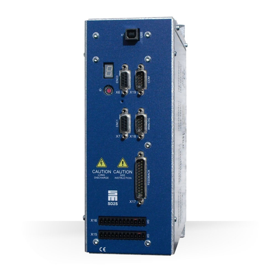
Page 35: Connectors
Device Description Connectors Fig. 5: Connectors on the device variants 0362149xy / 0362249xy / 0362129xy The gray-colored connectors are only available on the following device variants: X6, X7, X17 (measuring systems): 0362149xy, 0362249xy ▶ X64, X65 (EtherCAT option):0362249xy ▶ Connector Meaning Description Address selection switch of device... - Page 36 Device Description Connector Meaning Description External ballast resistor page 52 X64 OUT EtherCAT slave output page 52 X65 IN EtherCAT slave input Device housing ground page 78 SK 14 Mounting holes for shield connection clamp SK 14 by Phoenix page 77 (comprised in connector kit) You can order the appropriate connector kit for the device variants 0362X49xy and 0362129xy at SIEB &...
-
Page 37: Connector Pin Assignment
Connector Pin Assignment Connector Pin Assignment Operation of the Terminal Connectors 7.1.1 Click & Lock System (STCL Connectors) Plugging the connector [A] ▶ Plug the connector as shown in the figure on the housing and ensure that the connector locks in place (1.). Note: Both side guides must be fully pushed back to ensure that the connector locks firmly in place and to prevent unwanted loosening of the connector (e.g. -
Page 38: X6 - Encoder 0
Connector Pin Assignment (When the device is connected via SERVOLINK 4 only 12 addresses are available (0 to B).) The addresses of several devices in a system must be different from each other to ensure that they can be identified by the software. X6 –... -
Page 39: X14 - Usb
Connector Pin Assignment Related topics Connection example: "X6, X7 – Incremental Encoder with TTL Signals", page 55 Connection example: "X7 – Encoder Emulation", page 56 X14 – USB Communication interface to the connected PC 4-pole female USB connector, type B Name Description 5 V voltage supply for USB... -
Page 40: X15 - Digital Outputs
Connector Pin Assignment Related topics Connection example: "safety circuit (STO)", page 56 Safety function STO: "Safety Circuit / Restart Lock (STO)", page 95 X15 – Digital Outputs If you want to make use of the digital inputs and outputs, connect pin 9 to 24 V. -
Page 41: Digital Outputs- Vf
Connector Pin Assignment Mating connector Name Configurable functions VCC IO 24 V supply for the outputs 24 V auxiliary voltage for the outputs (24 V ±10 %, uncontrolled, max. 0.25 A) Ground (pin coded) Ground Parallel operation with other SD2S drive amplifiers or external components is not possible. Specification of terminal connections ▶... -
Page 42: X16 - Digital Inputs
Connector Pin Assignment Mating connector Name Configurable functions VCC IO 24 V supply for the outputs 24 V auxiliary voltage for the outputs (24 V ±10 %, uncontrolled, max. 0.25 A) Ground (pin coded) Ground Parallel operation with other SD2S drive amplifiers or external components is not possible. Specification of terminal connections ▶... - Page 43 Connector Pin Assignment Mating connector Name Configurable functions ▶ Operation enabled with error reset ▶ Error reset ▶ External hardware OK ▶ Speed direction ▶ MOP up ▶ MOP down ▶ Reducing current limitation / Imax ▶ No function ▶ Pos.
-
Page 44: Digital Inputs - Vf
Connector Pin Assignment 7.8.2 Digital Inputs – VF If more than 8 parameter sets are used, not all functions can be assigned freely anymore. If more than 32 parameter sets are used, the measuring system NAMUR can not be used anymore. 12-pole Mini-Combicon connector, suitable for mating connector MC 1,5/ 12-ST-3,81 (Phoenix) Mating connector... -
Page 45: X17 - Motor Feedback
Connector Pin Assignment Mating connector Name Configurable functions TEMP Motor temperature sensor (against GND) Reference speed value (reference to ground) (pin coded) AIN0+ Ground Ground See also X17. drivemaster2 : Activate the para‐ In order to use this analog input make the following setting in the software meter “Single-ended”... -
Page 46: X18 - Analog Interface
Connector Pin Assignment 25-pole male submin D connector Name Meaning Resolver S2 Resolver S1 Resolver R3 Resolver R1 Resolver S4 Resolver S3 COS- SinCos/linear Hall Cosine- COS+ SinCos/linear Hall Cosine+ SIN- SinCos/linear Hall Sine- SIN+ SinCos/linear Hall Sine+ Hall sensor 12 V track C / digital 5 V input 4 HALL_C / IN4 Hall sensor 12 V track B / digital 5 V input 3 HALL_B / IN3... - Page 47 Connector Pin Assignment 9-pole male submin D connector Name Configurable functions SERVO / VECTOR (SVC) AIN1- Reference point of AIN1+ (pin 2) AIN1+ ▶ No function ▶ No function ▶ Speed reference value ▶ Speed reference value ▶ Current reference value ▶...
-
Page 48: X19 - Com1 / Operating Terminal
Connector Pin Assignment 7.11 X19 – COM1 / Operating Terminal 9-pole male submin D connector Name Meaning 5.3 V (power supply for optional oper‐ ating terminal, short-circuit proof) Receive data Transmit data CAN_L CAN_L Ground Receive data 2 Transmit data 2 CAN_H CAN_H Ground... -
Page 49: Preparation Of Optical Fiber Cables With Connector
Connector Pin Assignment 7.12.1 Preparation of Optical Fiber Cables with Connector Every optical fiber connector requires an optical fiber cable with a male connector. The following information apply for connectors used in applications with 1 mm standard plastic optical fibers (POF). Technical data Rated value Storage temperature... -
Page 50: X44 - Power Supply
Connector Pin Assignment Article SIEB & MEYER article number Grinding paper 47000003 7.13 X44 – Power Supply Device variants: 0362X... 29xF 49xF 29xC 49xC 1-phase power supply – – ✔ ✔ 3-phase power supply ✔ ✔ ✔ ✔ 4-pole Power-Combicon connector, suitable for mating connector SPC 5/ 4-STCL-7,62 (Phoenix) with Click &... -
Page 51: X45 - Motor Connection
Connector Pin Assignment 7.14 X45 – Motor Connection 4-pole Power-Combicon connector, suitable for mating connector SPC 5/ 4-STCL-7,62 (Phoenix) with Click & Lock system (see STCL, page Mating connector X45 Name Coding Meaning Motor phase U Motor phase V Coded Motor phase W Protective conductor Specification of terminal connections:... -
Page 52: X63 - External Ballast Resistor
Connector Pin Assignment 7.15 X63 – External Ballast Resistor DANGER High voltages in the intermediate circuit Note that even after the device unit has been switched off high voltages may occur in the intermediate circuit of the complete system that can cause serious injuries. Wait until the intermediate circuit is fully discharged before cutting the connections of the external ballast resistor ("capacitor discharge"). - Page 53 Connector Pin Assignment The EtherCAT interface is only available with the following device variants: 0362249xy. 2 × 8-pole female RJ45 connector X64/X65 Name Description Transmit data + TX− Transmit data − Receive data + n.c. n.c. RX− Receive data − n.c.
- Page 54 Connector Pin Assignment Drive System SD2S - Hardware Description 0362X49xy / 0362129xy...
-
Page 55: Connection Examples
Connection Examples Connection Examples The following sections provide connection examples for the individual connectors of the device. A wiring example for the device connection it to find in the Appendix, page 107. X6, X7 – Incremental Encoder with TTL Signals Encoder signals: 5V Drive System SD2S - Hardware Description 0362X49xy / 0362129xy... -
Page 56: X7 - Encoder Emulation
Connection Examples X7 – Encoder Emulation The transmission meets the requirements of the standard TIA/EIA-422-B with a voltage differential of at least. ±0.9 V. safety circuit (STO) See also chapter 12 "Safety Circuit / Restart Lock (STO)", page Drive System SD2S - Hardware Description 0362X49xy / 0362129xy... -
Page 57: Wiring With Ossd
Connection Examples 8.3.1 Wiring with OSSD OSSD = Output Signal Switching Device 8.3.2 Wiring without OSSD OSSD = Output Signal Switching Device X15 – Digital Outputs / NAMUR Sensor / PULSE IN / Digital Field Plate / GMR 8.4.1 Digital Outputs The meanings of the digital outputs can be defined by parameters. -
Page 58: Namur Sensor
Connection Examples 8.4.2 NAMUR sensor As required by the NAMUR standard the switching threshold for the input is 2.5 mA. 8.4.3 PULSE IN 24 V A pulse generator for 5 V is to be connected at connector X17 (pin 25), see connection example section 8.6.11 "PULSE IN 5 V", page Drive System SD2S - Hardware Description 0362X49xy / 0362129xy... -
Page 59: Digital Field Plate / Gmr
Connection Examples 8.4.4 Digital Field Plate / GMR The switching thresholds of the converter input IN8 are 5.4 V for active-low signals and 5.9 V for active-high signals. Therefore the switching thresholds of the used sensor must be adapted to the input by offsetting the middle voltage. The resistors R and R depend on the used sensor. -
Page 60: Pulse (Speed Pulses)
Connection Examples 8.4.5 PULSE (Speed Pulses) X16/17 – Digital Inputs Digital inputs at X16 The meanings of the digital inputs can be defined by parameters. Yet another digital input is located at the connector X15, pin 6. Digital inputs (5 V) at X17 The following figure is a wiring example for a 5 V limit switch: Drive System SD2S - Hardware Description 0362X49xy / 0362129xy... -
Page 61: X17 - Motor Feedback
Connection Examples X17 – Motor Feedback 8.6.1 Resolver NOTICE Voltage (VCC) varies depending on the set measuring system When the connected measuring system is operated under a wrong voltage, it can be damaged. Check that you have chosen the right measuring system in the software before connecting. -
Page 62: Incremental Encoder With Sine Signals (1 V Pp )
Connection Examples 8.6.2 Incremental Encoder with Sine Signals (1 V NOTICE Voltage (VCC) varies depending on the set measuring system When the connected measuring system is operated under a wrong voltage, it can be damaged. Check that you have chosen the right measuring system in the software before connecting. -
Page 63: Linear Hall Encoder (1 V Pp )
Connection Examples 8.6.3 Linear Hall Encoder (1 V NOTICE Voltage (VCC) varies depending on the set measuring system When the connected measuring system is operated under a wrong voltage, it can be damaged. Check that you have chosen the right measuring system in the software before connecting. -
Page 64: Endat 2.1 With Sine Signals (1 V Pp )
Connection Examples 8.6.4 EnDat 2.1 with Sine Signals (1 V NOTICE Voltage (VCC) varies depending on the set measuring system When the connected measuring system is operated under a wrong voltage, it can be damaged. Check that you have chosen the right measuring system in the software before connecting. -
Page 65: Hiperface With Sine Signals
Connection Examples 8.6.5 Hiperface with Sine Signals NOTICE Voltage (VCC) varies depending on the set measuring system When the connected measuring system is operated under a wrong voltage, it can be damaged. Check that you have chosen the right measuring system in the software before connecting. -
Page 66: Hall Sensor
Connection Examples 8.6.6 Hall Sensor 12 V NOTICE Voltage (VCC) varies depending on the set measuring system When the connected measuring system is operated under a wrong voltage, it can be damaged. Check that you have chosen the right measuring system in the software before connecting. -
Page 67: Hall Sensor 5.3
Connection Examples 8.6.7 Hall Sensor 5.3 V NOTICE Voltage (VCC) varies depending on the set measuring system When the connected measuring system is operated under a wrong voltage, it can be damaged. Check that you have chosen the right measuring system in the software before connecting. -
Page 68: Field Plate
Connection Examples 8.6.8 Field Plate NOTICE Voltage (VCC) varies depending on the set measuring system When the connected measuring system is operated under a wrong voltage, it can be damaged. Check that you have chosen the right measuring system in the software before connecting. -
Page 69: Incremental Encoder With Ttl Signals (5.3 V)
Connection Examples 8.6.9 Incremental Encoder with TTL Signals (5.3 V) NOTICE Voltage (VCC) varies depending on the set measuring system When the connected measuring system is operated under a wrong voltage, it can be damaged. Check that you have chosen the right measuring system in the software before connecting. -
Page 70: Incremental Encoder
Connection Examples 8.6.10 Incremental Encoder 12 V NOTICE Voltage (VCC) varies depending on the set measuring system When the connected measuring system is operated under a wrong voltage, it can be damaged. Check that you have chosen the right measuring system in the software before connecting. -
Page 71: Pulse In 5 V
Connection Examples 8.6.11 PULSE IN 5 V NOTICE Voltage (VCC) varies depending on the set measuring system When the connected measuring system is operated under a wrong voltage, it can be damaged. Check that you have chosen the right measuring system in the software before connecting. -
Page 72: X18 - Analog Inputs/Outputs
Connection Examples The temperature sensor must have an internal resistor between 250 Ω and 2 kΩ. If no motor temperature sensor is connected, the input must be connected with GND. X18 – Analog Inputs/Outputs 8.7.1 Analog Outputs Configurable output voltage: 0 to +10 V, max. 1 mA Drive System SD2S - Hardware Description 0362X49xy / 0362129xy... -
Page 73: Analog Inputs
Connection Examples 8.7.2 Analog Inputs Voltage interface with input voltage range: ±10 V Can also be connected to potentiometer (500 Ω - 5 kΩ) X19 – Bus Connection 8.8.1 COM1 – RS232 Drive System SD2S - Hardware Description 0362X49xy / 0362129xy... -
Page 74: Can Bus
Connection Examples If you connect to a standard RS232 interface of a PC (9-pole male submin D connector), the used cable must look like this: Additional RS232 connection available: 8.8.2 CAN Bus The CAN interface is designed according to ISO 11898. It is a two-wire connection with differential signals. -
Page 75: X26/X27 - Servolink
Connection Examples The number of bus nodes is also limited by the specification according to ISO 11898. The limiting value is between 32 and 100 bus nodes. depending on the used cable and transmission rate. For further information on the maximum number of bus nodes refer to the document “CAN Physical Layer”... -
Page 76: X45 - Motor Phases
Connection Examples 8.11 X45 – Motor Phases Ground the motor housing in the machine! DANGER Dangerous shock currents Earthing and shielding measures are required to protect devices and persons. To ensure the safety of the operator earthing must be carried out with low impedance. With respect to the ground connection one of the following actions must be done: ▶... -
Page 77: Shielding Of The Motor Cable
Connection Examples Related topics Chapter "Motor Cable", page 92 8.12 Shielding of the Motor Cable For the operation of SD2S the motor cable needs to be shielded. Depending on the device and application more shielding measures might be required. The following examples explain how to connect the motor cable shield to the device housing using a shield connection clamp by Phoenix (see Manufacturers, page 112). -
Page 78: X64/X65 - Ethercat
Connection Examples 8.14 X64/X65 – EtherCAT Ethernet connection cable: To connect EtherCAT devices use only Ethernet cables of Category 5 (Class D) and higher. You can either use patch cables (1:1) or crossover cables (TX crosslinked to RX) because the receiver ports (PHY) support automatic cable recognition (auto crossover feature). -
Page 79: Setup
Setup Setup When connecting and setting up the installation consider the safety instruc‐ tions and the manual “Unit Assembly Complying EMC”. SD2S Connection and Switch-on For wiring also read the chapter 11 "General Information Regarding the Wiring", page The following connectors must be wired at the least: ▶... - Page 80 Setup Drive System SD2S - Hardware Description 0362X49xy / 0362129xy...
-
Page 81: Status Display And Error Messages
Status Display and Error Messages Status Display and Error Messages 10.1 LED Status Display: EtherCAT Connection Fig. 7: EtherCAT LEDs (device bottom side) Color Status Meaning Green Data transmission (TX) active Yellow Speed = 100 MBit Green Data reception (RX) active Yellow Speed = 100 MBit Color... -
Page 82: 7-Segment Display
Status Display and Error Messages 10.2 7-segment display The 7-segment display shows status and error messages. A status message is made up of 1 to 5 digits and displayed as sequence. All messages end with dot behind the last digit. When the first digit is 'E.', there is a permanent error. If the cause of an error can be specified, the display indicates the actual error code followed by a hyphen and a one-digit sub error code. -
Page 83: List Of Drive Error Messages
Status Display and Error Messages 10.2.2 List of Drive Error Messages The following messages apply to the entire SD2x drive series. According to the device type or operating mode, certain messages may not appear. Code Error message Error reaction Possible reason Interpolation error (interpolated Motor is stopped by quick stop ▶... - Page 84 Status Display and Error Messages Code Error message Error reaction Possible reason Communication node monitoring: Node Guarding monitoring time expired (configu‐ rable) Error in EtherCAT EEPROM EEPROM error Heartbeat monitoring: monitoring 2, 3, 4 Heartbeat / Watchdog time expired (configurable) Mains 'Ready for operation' is Motor is stopped by parameter- ▶...
- Page 85 Status Display and Error Messages Code Error message Error reaction Possible reason Power supply load monitoring -> Power supply unit will be discon‐ ▶ DC link was not precharged to the (0x522) mains voltage too low nected from mains. minimum voltage level in the set (1314 time period;...
- Page 86 Status Display and Error Messages Code Error message Error reaction Possible reason 1, 2, 3 4 EMF monitoring Flux monitoring Over current monitoring Under flux monitoring Minimum speed monitoring 2, 3 1, 2 Error during alignment Current limitation V/f oscil‐ lates Short circuit in power output stage Drive is immediately disabled,...
-
Page 87: List Of Warning Messages
Status Display and Error Messages Code Error message Error reaction Possible reason Communication error Safety function SFM/SLOF: between DSP and safety communication between DSP and controller safety controller is disturbed Drive parameters not activated Power output stage can not be ▶... -
Page 88: Message Of The Quick Stop Functions
Status Display and Error Messages Code Description DC link voltage less than parameterized warning threshold W09 Speed controller in current limitation / PI limit Position/tracking error greater than parameterized warning threshold W11 Speed error greater than parameterized warning threshold W12 Tracking error of the current too great Ambient temperature greater than parameterized warning threshold W14 Ballast resistor load greater than parameterized warning threshold W15 (ballast resistor I²t) -
Page 89: General Information Regarding The Wiring
General Information Regarding the Wiring General Information Regarding the Wiring 11.1 Mains Connection NOTICE Property damage due to incorrect mains connection Direct connection to ungrounded / asymmetrically grounded mains (IT mains with start point / IT delta mains) can destroy the devices. Connecting the device to this mains type is only possible with isolating transformer. - Page 90 General Information Regarding the Wiring ▶ The cable shields must be connected to the connector shell inside of the connec‐ tors. In the switch cabinet they should be connected to a ground bus. ▶ Cable shields not ending in a connector inside of the switch cabinet such as motor cables must be connected to the ground bus.
- Page 91 General Information Regarding the Wiring Ambient temperature T [°C] Correction factor 1.00 0.91 0.82 0.71 0.58 Cross-sections of round conductors The standard values of the cross-section of round copper conductors as well as the approximate ratio of metric ISO and AWG/MCM values are shown in the following table.
-
Page 92: Motor Cable
General Information Regarding the Wiring 11.2.1 Motor Cable DANGER Dangerous shock currents Earthing and shielding measures are required to protect devices and persons. To ensure the safety of the operator earthing must be carried out with low impedance. With respect to the ground connection one of the following actions must be done: ▶... -
Page 93: Communication Cable
General Information Regarding the Wiring Requirements to the motor cable The maximum admissible length of the motor cable is 100 m. The capacity must not exceed 5.2 nF. Example: If the cable capacity is 0.26 nF per meter, the maximum admissible length of the motor cable is 20 m. -
Page 94: Cables For The External Ballast Resistor
General Information Regarding the Wiring 11.2.4 Cables for the External Ballast Resistor The cables of the external ballast resistor of R and +UB must be twisted. If the cable is longer than 20 cm a shielded cable must be used. Drive System SD2S - Hardware Description 0362X49xy / 0362129xy... -
Page 95: Safety Circuit / Restart Lock (Sto)
Safety Circuit / Restart Lock (STO) Safety Circuit / Restart Lock (STO) according to EN ISO 13849-1:2008-12, DIN EN 62061:2005 SIL 3 ▶ The restart lock is provided for preventing an unintentional start of a speed-variable drive from the standstill and can, for example, be used in the machine function “safe stop”. -
Page 96: Functional Description Of The Restart Lock
Safety Circuit / Restart Lock (STO) DANGER Danger due to electric shock The restart lock does not galvanically separate the output stages from the motor. Thus, the restart lock does not protect against electric shock. The complete machine must always be galvanically separated from the mains by use of the main switch(DIN EN 60204-1 5.3) for any interruptions of the operation, maintenance, repair or cleaning work at the machine or system. -
Page 97: Wiring Example
Safety Circuit / Restart Lock (STO) If the OSSD signals or at least one of the +24 V conductors fail, the safety circuit switches the pulse pattern of the output stage control sectors off. The response time of the restart lock is max. 4 ms. The restart lock must only be controlled when ▶... -
Page 98: Requirements And Standards
Safety Circuit / Restart Lock (STO) Circuit with OSSD (SIL 3) The following figure shows a circuit without OSSD safety device, whilst only safety directed command devices with forcibly opened contacts in two-channel design are used. SIL 3 (according to EN ISO 13849-1) is achieved. It is also possible to cascade several different safe emergency stop devices, position switches or door locks to one safety circuit. -
Page 99: Restart Lock Procedure
Safety Circuit / Restart Lock (STO) The safety concept K1 meets the requirements of SIL 3 according to the standards named above. Requirements according to DIN EN 61800-5-2:2014-06 When connected appropriately, the safety concept K1 does not supply any share of dangerous, undetected errors in the safety chain for the function STO. - Page 100 Safety Circuit / Restart Lock (STO) Fig. 9: STO restart lock procedure - Timing and required actions Use case A If a STO contact is interrupted during "Switch off", the device status turns to "Switch On Disabled". As soon as the STO contact is closed again, you can restart the device with the next "Switch on".
-
Page 101: Appendix
Appendix Appendix 13.A Specification of Drive Functions Devices of the series SD2S can operate with different drive functions depending on the loaded drive software. The different drive functions support different motors and motor measuring systems. The available drive functions depend on the device type and device version. ▶... - Page 102 Appendix Drive function SERVO / VECTOR SVC: ▶ Synchronous rotative ▶ 2000 rotating field frequency Software Drive function SERVO / VECTOR L04001Vxxxxx & F04001Vxxxxx L09005Vxxxxx & F09005Vxxxxx Software packages ▶ special function: EnDat 2.1 L04001Vxxxxx & F04003Vxxxxx L04002Vxxxxx & F04013Vxxxxx ▶...
- Page 103 Appendix Operating mode Drive function SERVO / VECTOR Operating modes ▶ Speed Mode ▶ Speed Mode ▶ Current reference value ▶ Profile Velocity Mode ▶ Interpolated position control ▶ Electronic gear Software Connection Drive function SERVO / VECTOR Parameterization in soft‐ ▶...
- Page 104 Appendix Drive function SERVO / VECTOR ▶ Maximum range 0 – 10 V ▶ Resolution internal 14 Bit ▶ Sampling 4 kHz (250 µs) ▶ Function to be configured via software Encoder ENC0 ▶ Input ▶ Signal A Quad B, pulse/direction, CW/CCW ▶...
-
Page 105: Specification Of Device Firmware
Appendix B: Specification of Device Firmware 13.B Specification of Device Firmware The following firmware variants are available for the drive amplifiers of the series SD2S(0362149xy/0362249xy). Please consider that some device variants do not provide all connections specified in the firmware. SD2S firmware (without version number vxxxxx) SERVO / VECTOR... - Page 106 Appendix B: Specification of Device Firmware SD2S firmware (without version number vxxxxx) EtherCAT ✔ Internal setpoints ✔ ✔ ✔ Motor potentiometer ✔ ✔ ✔ Encoder 0 / pulse direction input ✔ Encoder Emulation AB quadrature signals ✔ ✔ ✔ ✔ ✔...
-
Page 107: C Wiring Example
Appendix C: Wiring Example 13.C Wiring Example 13.C Drive System SD2S - Hardware Description 0362X49xy / 0362129xy... - Page 108 Appendix C: Wiring Example 13.C Drive System SD2S - Hardware Description 0362X49xy / 0362129xy...
-
Page 109: D Manufacturers
Appendix D: Manufacturers 13.D Manufacturers 13.D.1 SIEB & MEYER Accessories In the following you find all accessories for SD2S that you can order at SIEB & MEYER. Consider the information on accessories suitable for your device in the tech‐ nical manual. 13.D.1.1 Connectors of the Series SD2S Connector/cable kits... -
Page 110: Line Filters For Frequency Converter/Power Electronics
Appendix D: Manufacturers 13.D.1.4 Line Filters for Frequency Converter/Power Electronics Line Filters by TDK & EPCOS Group ▶ 1-phase and 3-phase line filters ▶ high attenuation ▶ partial RCD compatibility The maximum current (I ) must be adapted to the back-up fuses of the device. -
Page 111: Usb>Rs232/485 Converter 050201
Appendix D: Manufacturers 13.D.1.6 USB>RS232/485 Converter 050201 The USB>RS232/485 Converter can be ordered at SIEB & MEYER as an optional accessory for device configuration. This converter is developed especially for the amplifier series SD2x. Via the converter the devices can communicate with a PC without RS232 or RS485 interface. -
Page 112: Shield Connection Clamps
Appendix D: Manufacturers Phoenix article number Description 2905470 Surge arrestor FLT-SECT1+T2-3S-350/25-FM: with separate PE and N (L1, L2, L3, PE, N) 13.D.2.2 Shield Connection Clamps Shield connection clamps for EMC busbar and for motor/power or measuring system connection of the devices Phoenix article number Name Connection method... -
Page 113: Index
Index Index 0362129xy ID switch 0362149xy Initial Operation 0362249xy 050201 7-segment display LED status display Line cross-sections Line filters Accessories Mains chokes Block diagram Manufacturers Motor cable Mounting Cable requirements Click & Lock connectors Connectors Operating states Optical filer connector (POF) preparation of optical fiber cables with connector Dimensions... - Page 114 Index Technical data Type plate USB cable USB>RS232/485 converter Wall mounting Warning messages Wiring example Wiring instructions X10 – safety (STO) X14 – USB X15 – digital OUT X16 – digital IN X17 – motor feedback X18 – analog X19 – COM1 / operating terminal X26 –...
Need help?
Do you have a question about the SD2S 0362X49xy and is the answer not in the manual?
Questions and answers
We are using a Sieb&Meyer SD2S inverter. The 7-segment LED does not light up. Is there any internal protection?