Table of Contents
Advertisement
Available languages
Available languages
Quick Links
Sicherheitsschaltgerät / Safety Relay / Relais de sécurité
Betriebsanleitung
ELMON relay 31 Sicherheitsschaltgerät
Operati ng Manual
ELMON relay 31 Safety Relay
Manuel d´uti lisati on
ELMON relay 31 Relais de sécurité
ELMON relay 31
(Original, Gülti gkeit siehe letzte Seite)
(see last page for validity)
(Validité voir la dernière page)
Seite 3-12
Page 13-22
Page 23-32
Advertisement
Chapters
Table of Contents

Subscribe to Our Youtube Channel
Related Manuals for ASO Safety Solutions ELMON 31


Summary of Contents for ASO Safety Solutions ELMON 31
- Page 1 Sicherheitsschaltgerät / Safety Relay / Relais de sécurité ELMON relay 31 Betriebsanleitung (Original, Gülti gkeit siehe letzte Seite) Seite 3-12 ELMON relay 31 Sicherheitsschaltgerät Operati ng Manual (see last page for validity) Page 13-22 ELMON relay 31 Safety Relay Manuel d´uti lisati on (Validité voir la dernière page) Page 23-32 ELMON relay 31 Relais de sécurité...
- Page 2 Übergabedokumentation / Documentation / Documentation de datation / Documentazione di consegna / Documentatie Anlagenbeschreibung / Description / Description du système / Descrizione impianto / Beschrijving van de installatie Anlagenart / Type of plant / Sorte du système / Tipo d’impianto / Type installatie Hersteller / Manufacturer / Fabricant / Produttore / Fabrikant Seriennummer / Serial number / Numéro de série / Numero di serie / Seriennummer Datum der Inbetriebnahme / Commissioning date / Date de mise en marche / Data della messa in funzione...
-
Page 3: Table Of Contents
ELMON relay 31-31 Sicherheitsschaltgerät Inhaltsverzeichnis Inhaltsverzeichnis . . . . . . . . . . . . . . . . . . . . . . . 3 Allgemeine Sicherheitsbestimmungen und S chutzmaßnahmen . -
Page 4: S Chutzmaßnahmen
Sicherheitsschaltgerät 2. Allgemeine Sicherheitsbestimmungen und Schutzmaßnahmen • Hersteller und Benutzer der Anlage / Maschine, an der die Schutzeinrichtung verwendet wird, sind dafür verantwortlich, alle geltenden Sicherheitsvorschriften und -regeln in eigener Verantwortung abzustimmen und einzuhalten. • Die Schutzeinrichtung garantiert in Verbindung mit der übergeordneten Steuerung eine funktionale Sicherheit, nicht aber die Sicherheit der gesamten Anlage / Maschine. Vor dem Einsatz des Gerätes ist deshalb eine Sicherheitsbetrachtung der gesamten Anlage / Maschine nach der Maschinenrichtlinie 2006/42/EG oder nach entsprechender Produktnorm notwendig. -
Page 5: Allgemeines
ELMON relay 31-31 Sicherheitsschaltgerät 3. Allgemein Das einkanalige Schaltgerät ELMON relay 31 fi ndet seine Anwendung bei der Auswertung von Sicherheits- kontaktmatt en, sowie bei der Absicherung von Quetsch- und Scherstellen durch Sicherheitskontaktleisten und Sicherheitsbumpern (Signalgeber). Das Schaltgerät ELMON relay 31 ist für den Einsatz an Anlagen/Maschinen vorgesehen, die durch eine über- geordnete Steuerung ein Testsignal vor jeder gefährlichen Bewegung zur Verfügung stellt. In Verbindung mit dem Testsignal erfüllt das Schaltgerät die Sicherheits-Kategorie 2 nach EN ISO 13849-1:2015 „Sicher- heitsbezogene Teile von Steuerungen“... -
Page 6: Ausführungen Und Mechanische Befestigung
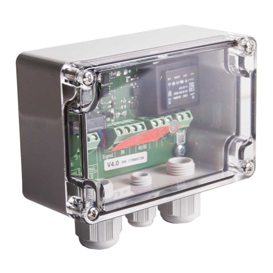
Sicherheitsschaltgerät 5.3 Ausführungen und mechanische Befestigung Ausführung ELMON relay 31-31 Polycarbonat-Gehäuse mit Verschraubungen 1 x M12 und 2 x M16 für Aufputzmontage in rauer Umgebung. Das Schaltgerät ist fachgerecht an einem geeigneten Montageort zu befestigen. Nach Entfernen des Deckels kann das Gehäuse mit vier Schrauben befestigt werden. Die Einbaulage des Schaltgerätes ist beliebig, sollte jedoch zum Schutz vor eindringender Feuchtigkeit so montiert werden, dass die Kabeleinführungen nach unten zeigen. Ausführung ELMON relay 31-31W Wie Version ELMON relay 31-31, jedoch mit Wechslerausgang (Ausgänge 12 13 14). Technisch bedingt entspricht die Zuordnung der Ausgänge nicht die der Version ELMON relay 31-31 (siehe Seite 10). -
Page 7: Testung
ELMON relay 31-31 Sicherheitsschaltgerät 6.3 Testung Für eine normenkonforme Auslegung der Schutzeinrichtung muss die übergeordnete Maschinensteuerung eine Testung vor jeder gefährlichen Bewegung oder in der ungefährlichen Phase/Bewegung der Maschine durchführen. Mit Anlegen des Testsignals muss der Ausgangskontakt des Schaltgerätes öff nen. Diese Schalt- zustandsänderung muss durch die übergeordnete Maschinensteuerung ausgewertet werden. Im korrekten Testf all leitet die Maschinensteuerung daraufh in die Fahrbewegung oder den nächsten Arbeitsschritt ein. Andernfalls muss die Steuerung eine Fehlermeldung ausgeben und das kraft betriebene Arbeitsmitt el (z.B. Motor) ein Abschaltsignal von der Maschinensteuerung erhalten. Mit dem DIP-Schiebeschalter kann das zur Verfügung stehende Testsignal selekti ert werden. -
Page 8: Anwendungsbeispiel
Sicherheitsschaltgerät 6.5 Anwendungsbeispiel Sicherheitsgerichtete Überwachung von einem Signalgeberstromkreis mit übergeordneter SPS oder Maschi- nensteuerung . Zur Funktionskontrolle der Schutzeinrichtung führt die SPS/Maschinensteuerung eine Testung vor jeder gefährlichen Bewegung oder in der ungefährlichen Phase/Bewegung der Maschine durch. Im korrekten Testfall leitet die SPS/Maschinensteuerung daraufhin die Fahrbewegung oder den nächsten Arbeitsschritt ein. 24VDC L1 L2 L3 I1.1 Test Signal ELMON relay 31-31 Steuerung Q1.1 Q1.2 0VDC... -
Page 9: Anschluss Von Mehreren Signalgebern Pro Signalgeberkreis
ELMON relay 31-31 Sicherheitsschaltgerät 6.6 Anschluss von mehreren Signalgebern pro Signalgeberkreis ASO-Signalgeber dürfen nicht parallel geschaltet werden. Das Schaltgerät ELMON relay 31 verfügt über nur einen Eingang für Signalgeber . An dem Signalgebereingang X1 X2 können ein oder mehrere Signalgeber (z.B. Sicherheitskontaktleisten) angeschlossen werden. Hierfür werden die einzelnen Signalgeber entsprechend Bild 1 in Serie geschaltet. Sicherheitskontaktleiste SENTIR edge: Es können maximal 5 SENTIR edge in Serie geschaltet werden. Die maximale Gesamtlänge der SENTIR edge darf 100 m nicht überschreiten . -
Page 10: Fehlerdiagnose
Sicherheitsschaltgerät 8. Fehlerdiagnose Bei korrekter Verdrahtung und Anlegen der Versorgungsspannung darf nur die LED Power grün leuchten . Bei Aufleuchten einer der anderen LED‘s ist ein Fehler im System vorhanden, der sich mit Hilfe der LED‘s eingrenzen lässt. Fehler Fehlerbeseitigung Anschlüsse und LED‘s leuchten nicht Versorgungsspannung Versorgungsspannung überprüfen: fehlt, zu gering oder falsch 12-24 V AC/DC: 12-24 V AC/DC angeschlossen Toleranzbereich: +10% L1,N,PE: 230 V AC 50-60Hz LED Actuate leuchtet Zuleitung Signalgeber oder Anschlüsse, Verdrahtung und Zuleitungen Signalgeber fehlerhaft des Signalgebers überprüfen (abgequetschte Zuleitungen, brüchige Zuleitungen etc.). Signalgeber überprüfen* Testung fehlerhaft Dip-Schiebeschalter Einstellung überprüfen . -
Page 11: Technische Daten
ELMON relay 31-31 Sicherheitsschaltgerät 9. Technische Daten Versorgungsspannung Netzspannung: 230 V AC 50/60 Hz Netz Absicherung: T 1 A Kleinspannung: 12-24 V AC/DC +10% Leistungsaufnahme Netzteil 0,5 VA 230 V AC 0,5-1 VA 12-24 V AC/DC Rref Abschlusswiderstand Signalgeber Schaltrelais Nominalwert = 8,2 kΩ oberer Schaltwert > 12,7 kΩ unterer Schaltwert R < 4,6 kΩ Relais Stufen Uref Nennstrom DC... -
Page 12: Eg Konformitätserklärung
Sicherheitsschaltgerät 10. EG Konformitätserklärung ELMON relay 31-20 ELMON relay 31-20 ELMON relay 31-20 ELMON relay 31-30 ELMON relay 31-30 ELMON relay 31-30 ELMON relay 31-21 ELMON relay 31-21 ELMON relay 31-21 ELMON relay 31-31* (W) ELMON relay 31-31* (W) ELMON relay 31-31* (W) ELMON relay 31-33 (V) ELMON relay 31-33 (V) ELMON relay 31-33 (V) -
Page 13: Contents
ELMON relay 31-31 Safety Relay Contents Contents . . . . . . . . . . . . . . . . . . . . . . . . . . . 13 General safety regulations and protective measures . -
Page 14: General Safety Regulations And Protective Measures
Safety Relay 2. General safety regulations and protective measures • The manufacturer and users of the plant / machine on which the protection is being used are responsible for implementing and following all applicable safety regulations and rules. • When used in conjunction with the higher-order controller, the protection guarantees functional safety, but not the safety of the entire plant / machine. The safety of the entire plant / machine must, therefore, be assessed in accordance with machinery directive 2006/42/EC or appropriate product norm before using the device . • The operating manual must always be available at the place of installation of the protection. -
Page 15: General
ELMON relay 31-31 Safety Relay 3. General The ELMON relay 31 switching unit, designed with one channel, is used for evaluati ng safety contact mats and for safeguarding locati ons where there is a risk of crushing and cutti ng through the use of safety contact edges and safety bumpers (sensors). The ELMON relay 31 switching unit is intended for use on plants/machines that make a test signal available through a primary controller prior to each dangerous movement. In combinati on with the test signal, the switching unit sati sfi es safety category 2 acc. to EN ISO 13849-1:2015 "Safety-related parts of control systems" . Monitoring of the standby current is made possible by an integrated terminati ng resistor in the sensor. If the specifi ed standby current is fl owing, the output relay is acti vated and the switching contact is closed. If the sensor is actuated or the sensor circuit is interrupted, the relay switching contact opens. The monito- ring state of the sensor and the applied operati ng voltage are indicated by LEDs. -
Page 16: Versions And Mechanical Mounting
Safety Relay 5.3 Versions and mechanical mounting Version ELMON relay 31-31 Polycarbonate housing with 1 x M12 and 2 x M16 screw connections for on-wall mounting in harsh environ- ments . The switching unit is to be professionally mounted at a suitable location. After removing the cover, the housing can be mounted with four screws. The switching unit may be mounted in any orientation. To prevent moisture penetration, it should, however, be installed so that the cable conduits point downward. Version ELMON relay 31‑31W Same as version ELMON relay 31-31, but with changeover contact (outputs 12 13 14). For technical reasons, output assignments are not the same as those of version ELMON relay 31-31 (see page 20). 6. Commissioning 6.1 Prerequisites • When supplying with 12-24 V AC/DC, the voltage must comply with the requirements for safety low voltage (SELV). -
Page 17: Test
ELMON relay 31-31 Safety Relay 6.3 Test For a standard-compliant design of the protecti on, the primary machine control must perform a test prior to each dangerous movement or during the non-dangerous phase/movement of the machine. Upon appli- cati on of the test signal, the output terminal of the switching unit must open. This change in switching state must be evaluated by the primary machine control . If the test result is correct, the machine control then initi ates the movement or the next work step. Otherwise, the control must output an error message and the power-driven work equipment (e.g. motor) must receive a switch-off signal from the machine control. The available test signal can be selected with the DIP slide switch. Characteristi cs of the signal Test signal S1 Pos . -
Page 18: Example Of Use
Safety Relay 6.5 Example of use Safety-related monitoring of a sensor circuit with primary PLC or machine control. For a functional test of the protection, the PLC/machine control performs a test prior to each dangerous movement or in the non-dangerous phase/movement of the machine . If the test result is correct, the PLC/ machine control then initiates the movement or the next work step. 24VDC L1 L2 L3 I1.1 Test Signal ELMON relay 31-31 Q1.1 Q1.2 0VDC... -
Page 19: Connecting Multiple Sensors Per Sensor Circuit
ELMON relay 31-31 Safety Relay 6.6 Connecting multiple sensors per sensor circuit ASO sensors must not be connected in parallel. The ELMON relay 31 switching unit is only equipped with one input for sensors. Nevertheless, it is possible to connect two or more sensors to the switching unit. For this purpose, the individual sensors are connected in series according to figure 1. Safety contact edges SENTIR edge: Up to five SENTIR edge may be connected in series. The maximum total length oft the SENTIR edge shall not exceed 100 m . The length of one SENTIR edge may be up to 25 m. The total cable length oft the in series connected SENTIR edge must not exceed 25 m . Safety contact bumper SENTIR bumper: Up to five SENTIR bumper may be connected in series. The maximum total length oft the SENTIR bumper shall not exceed 15 m . -
Page 20: Error Diagnosis
Safety Relay 8. Error diagnosis Only the green Power LED may illuminate if the supply voltage has been correctly connected . If one of the other LEDs illuminates, there is an error in the system which can be pinpointed with the aid of the LED. Error Error correction LEDs are not illuminated The supply voltage is missing, Check connections and supply voltage: too low or has been connected 12-24 V AC/DC: 12-24 V AC/DC incorrectly Tolerance range: +10%... -
Page 21: Technical Specifications
ELMON relay 31-31 Safety Relay 9. Technical specifications Supply voltage Mains voltage: 230 V AC 50/60 Hz Mains Fuse protection T 1 A Low voltage: 12-24 V AC/DC +10% Power consumption Power unit 0,5 VA 230 V AC 0,5-1 VA 12-24 V AC/DC Rref Terminating resistor - sensor Relay nominal value = 8,2 kΩ upper switching point R > 12,7 kΩ... -
Page 22: Ec Declaration Of Conformity
Safety Relay 10. EC declaration of conformity ELMON relay 31-20 ELMON relay 31-20 ELMON relay 31-20 ELMON relay 31-30 ELMON relay 31-30 ELMON relay 31-30 ELMON relay 31-21 ELMON relay 31-21 ELMON relay 31-21 ELMON relay 31-31* (W) ELMON relay 31-31* (W) ELMON relay 31-31* (W) ELMON relay 31-33 (V) ELMON relay 31-33 (V) - Page 23 ELMON relay 31-31 Relais de sécurité Table des matières Table des matières . . . . . . . . . . . . . . . . . . . . . 23 Prescriptions générales de sécurité et mesures de protection .
-
Page 24: Prescriptions Générales De Sécurité Et Mesures
Relais de sécurité 2. Prescriptions générales de sécurité et mesures de protection • Le fabricant et l'utilisateur du système / de la machine sur lequel est placé le dispositif de protection, ont la responsabilité d'appliquer et de suivre toutes les directives et règles de sécurité en vigueur. • Le dispositif de protection associé à une commande appropriée garantit la sécurité fonctionnelle, mais pas celle de l'ensemble du système / de la machine. Avant l'emploi de l'appareil, une évaluation de la sécurité de l'ensemble du système / de la machine est donc indispensable conformément à la directive sur les machines 2006/42/CE ou à la norme de produit correspondante. -
Page 25: Généralités
ELMON relay 31-31 Relais de sécurité 3. Généralités Le relais de sécurité à un canal ELMON relay 31 sert pour l'évaluati on de tapis de sécurité et pour la protecti on contre les risques d'écrasement et de cisaillement à l'aide de barres palpeuses et de bumpers de sécurité (émett eurs de signaux). Le relais de sécurité ELMON relay 31 est conçu pour l'emploi sur des systèmes / machines qui, grâce à une commande supérieure, mett ent à dispositi on un signal de test avant chaque mouvement dangereux. Combiné au signal de test, le relais de sécurité répond aux exigences de la catégorie de sécurité 2 de la norme EN ISO 13849-1:2015 « Parti es des systèmes de commande relati ves à... -
Page 26: Modèles Et Fixation Mécanique
Relais de sécurité 5.3 Modèles et fixation mécanique Modèle ELMON relay 31-31 Boîtier en polycarbonate avec presse-étoupe 1 x M12 et 2 x M16 pour montage mural en environnement rude. Le relais de sécurité doit être fixé correctement à un emplacement adapté. Une fois le couvercle retiré, le boîtier peut être accroché à l'aide de quatre vis. La position de montage du relais de sécurité peut être quelconque. Pour le protéger contre l'humidité, il est toutefois recommandé de l'installer de telle façon que les entrées de câble soient orientées vers le bas. Modèle ELMON relay 31‑31W Comme modèle ELMON relay 31-31, mais avec sortie d'inverseur (sorties 12 13 14). Pour des raisons techniques, l'affectation des sorties ne correspond pas à celle de la version 31-31 (voir page 30). ELMON relay 6. Mise en service 6.1 Conditions • En cas d'alimentation par 12-24 V CA/CC, la tension doit répondre aux exigences de la très basse tension de protection (TBTP). • Les câbles posés en extérieur ou en dehors de l'armoire électrique doivent être protégés de façon appropriée . -
Page 27: Test
ELMON relay 31-31 Relais de sécurité 6.3 Test Pour la conformité aux normes du dispositi f de protecti on, la commande supérieure de la machine doit exé- cuter un test avant chaque mouvement dangereux ou pendant les phases et mouvements non dangereux de la machine. Lors de l'applicati on du signal de test, le contact de sorti e du relais de sécurité doit s'ouvrir. Ce changement d'état doit être exploité par la commande supérieure de la machine . Si le résultat du test est correct, la commande de la machine déclenche le mouvement ou l'opérati on suivante. Dans le cas contraire, la commande doit émett re un message d'erreur et l'équipement mécanique (p. ex. moteur) doit recevoir un signal de coupure de la commande de la machine. Le commutateur DIP permet de sélecti onner le signal de test souhaité... -
Page 28: Exemple D'utilisation
Relais de sécurité 6.5 Exemple d'application Contrôle de sécurité d'un circuit de signal avec API ou commande de machine supérieur. Pour le contrôle du fonctionnement du dispositif de protection, l'API ou la commande de la machine exécute un test avant chaque mouvement dangereux ou pendant les phases et mouvements non dangereux de la machine . Si le résultat du test est correct, l'API ou la commande de la machine déclenche le mouvement ou l'opération suivante. 24VDC L1 L2 L3 I1.1 Signal de test ELMON relay 31-31 Q1.1 Q1.2 0VDC... -
Page 29: Raccordement De Plusieurs Émetteurs De Signaux Par
ELMON relay 31-31 Relais de sécurité 6.6 Raccordement de plusieurs émetteurs de signaux par circuit de signal Les émetteurs de signaux ASO ne doivent jamais être montés en parallèle. Le relais de sécurité ELMON relay 31 ne dispose que d'une entrée pour émetteur de signaux. Il est toutefois possible de lui raccorder plusieurs émetteurs de signaux. Pour cela, les émetteurs de signaux individuels sont montés les uns après les autres comme illustré (figure 1). Barre palpeuse SENTIR edge: Il est possible de monter au plus 5 SENTIR edge en série . La longueur totale des SENTIR edge ne doit pas dépasser 100 m . -
Page 30: Diagnostic D'erreurs
Relais de sécurité 8. Diagnostic d'erreurs Si le câblage est correct, lors de la mise sous tension, seule la LED Power doit briller en vert . Si une des autres LED s'allume, il y a une erreur dans le système que la LED allumée permet de localiser. Erreur Correction Contrôler les Les LED ne brillent pas Pas d'alimentation, trop peu, raccordements et l'alimentation : mal branchée 12-24 V AC/DC : 12-24 V CA/CC tolérance : +10 %... -
Page 31: Données Techniques
ELMON relay 31-31 Relais de sécurité 9. Données techniques Tension d'alimentation Tension réseau 230 V CA 50/60 Hz réseau Protection: T 1A Tension d'alimentation Très basse tension 12-24 V CA/CC +10% Puissance absorbée Rref 0,5 VA 230 V CA Relais 0,5-1 VA 12-24 V CA/CC Résistance terminale de l'émetteur de signaux valeur nominale =8,2 kΩ... -
Page 32: Déclaration De Conformité Ce
Relais de sécurité 10. Déclaration de conformité CE ELMON relay 31-20 ELMON relay 31-20 ELMON relay 31-20 ELMON relay 31-30 ELMON relay 31-30 ELMON relay 31-30 ELMON relay 31-21 ELMON relay 31-21 ELMON relay 31-21 ELMON relay 31-31* (W) ELMON relay 31-31* (W) ELMON relay 31-31* (W) ELMON relay 31-33 (V) ELMON relay 31-33 (V) - Page 33 ELMON relay 31-31 Abmaße / Dimensions / Dimensions...
- Page 34 Sicherheitsschltgerät / Safety Relais / Relais de sécurité Notizen / Notes / Notes ..........
- Page 35 ELMON relay 31-31 Notizen / Notes / Notes ..........
- Page 36 Sicherheitsschltgerät / Safety Relais / Relais de sécurité 11 .DB .08 .071 Betriebsanleitung Rev 05 Deutsch Technische Änderungen vorbehalten . Für Irrtümer und Druckfehler kann keine Haftung übernommen werden. Diese Betriebsanleitung ist für folgende Versionsstände gültig: von V 4 .0 11 .DB .08 .071 Operating Manual Rev 05 English Subject to technical modifications. No liability can be assumed for errors or misprints . This operating manual is valid for the following versions: from V 4 .0 11 .DB .08 .071 Manuel d’utilisation Rév 05...
Need help?
Do you have a question about the ELMON 31 and is the answer not in the manual?
Questions and answers