Lincoln Electric LF-74 Operator's Manual
Wire feeder
Hide thumbs
Also See for LF-74:
- Technical specifications (8 pages) ,
- Service manual (119 pages) ,
- Operator's manual (60 pages)
Table of Contents
Advertisement
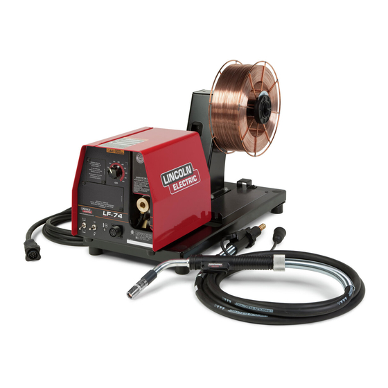
LF- 74 WIRE FEEDER
For use with machines having Code Numbers:
Safety Depends on You
Lincoln arc welding and cutting
equipment is designed and built
with safety in mind. However,
your overall safety can be
increased by proper installation ...
and thoughtful operation on your
part. DO NOT INSTALL, OPER-
ATE OR REPAIR THIS EQUIP-
MENT WITHOUT READING
THIS MANUAL AND THE SAFE-
TY PRECAUTIONS CONTAINED
THROUGHOUT. And, most
importantly, think before you act
and be careful.
• Sales and Service through Subsidiaries and Distributors Worldwide •
Cleveland, Ohio 44117-1199 U.S.A. TEL: 216.481.8100 FAX: 216.486.1751 WEB SITE: www.lincolnelectric.com
RETURN TO MAIN MENU
11195, 11196, 11197, 11610, 11611
11712, 11713
R
IP21
IEC 60974-5
OPERATOR'S MANUAL
• World's Leader in Welding and Cutting Products •
Copyright © Lincoln Global Inc.
IM872-B
March, 2010
Advertisement
Table of Contents
Troubleshooting

Related Manuals for Lincoln Electric LF-74


Summary of Contents for Lincoln Electric LF-74
- Page 1 IM872-B RETURN TO MAIN MENU LF- 74 WIRE FEEDER March, 2010 11195, 11196, 11197, 11610, 11611 For use with machines having Code Numbers: 11712, 11713 Safety Depends on You Lincoln arc welding and cutting equipment is designed and built with safety in mind. However, your overall safety can be increased by proper installation ...
- Page 2 351040, Miami, Florida 33135 or CSA Standard W117.2-1974. A Free copy of “Arc Welding Safety” booklet E205 is available from the Lincoln Electric Company, 22801 St. Clair Avenue, Cleveland, Ohio 44117-1199. BE SURE THAT ALL INSTALLATION, OPERATION, MAINTENANCE AND REPAIR PROCEDURES ARE PERFORMED ONLY BY QUALIFIED INDIVIDUALS.
- Page 3 SAFETY ARC RAYS can burn. ELECTRIC SHOCK can 4.a. Use a shield with the proper filter and cover kill. plates to protect your eyes from sparks and 3.a. The electrode and work (or ground) circuits the rays of the arc when welding or observing are electrically “hot”...
- Page 4 SAFETY WELDING and CUTTING CYLINDER may explode SPARKS can if damaged. cause fire or explosion. 7.a. Use only compressed gas cylinders 6.a. Remove fire hazards from the welding area. containing the correct shielding gas for the If this is not possible, cover them to prevent process used and properly operating the welding sparks from starting a fire.
- Page 5 SAFETY 5. Toujours porter des lunettes de sécurité dans la zone de PRÉCAUTIONS DE SÛRETÉ soudage. Utiliser des lunettes avec écrans lateraux dans les zones où l’on pique le laitier. Pour votre propre protection lire et observer toutes les instructions et les précautions de sûreté...
- Page 6 Electric for advice or information about their use of our products. We respond to our customers based on the best information in our posses- sion at that time. Lincoln Electric is not in a position to warrant or guarantee such advice, and assumes no liability, with respect to such infor- mation or advice.
-
Page 7: Table Of Contents
TABLE OF CONTENTS Page Installation .......................Section A Technical Specifications ..................A-1 Safety Precautions....................A-2 Location......................A-2 Mounting ......................A-2 Bench Mount ....................A-3 Swivel Mount....................A-3 Boom Mount....................A-3 Suspended ......................A-3 Weld Cable Sizes....................A-4 Coaxial Weld Cables..................A-5 Weld Cable Connections.................A-5 Analog Control Cable Connections................A-6 Analog Miller Control Cable Adapter ..............A-7 Welding Gun/Wire Feeder Trigger Connector..........A-8 High Frequency Protection................A-8 Remote Sense Lead Specifications ..............A-8... - Page 8 Page Maintenance ....................Section D Safety Precautions ....................D-1 Routine ........................D-1 Periodic........................D-1 Calibration Specification ................D-1, D-2 ________________________________________________________________________ Troubleshooting ......................E Safety Precautions....................E-1 How To Use Troubleshooting Guide..............E-1 Troubleshooting .....................E-2, E-3 ________________________________________________________________________ Wiring Diagram and Dimension Prints ............Section F ________________________________________________________________________ Parts Lists.......................P-518 ________________________________________________________________________ LF-74...
-
Page 9: Installation
INSTALLATION TECHNICAL SPECIFICATIONS: LF-74 Wire Feeder SPEC.# TYPE WIRE FEED SPEED RANGE Model Gearing GMAW FCAW WFS Range Wire Sizes WFS Range Wire Sizes 100 – 800 ipm 100 – 800 ipm .023 – 1/16" K2426-1 (2.5-20.3 m/min.) (2.5-20.3 m/min.) .030 - 5/64”... -
Page 10: Safety Precautions
(4 PLACES) (4 PLACES) ---------------------------------------------------------------------------------------- LOCATION The LF-74 may be placed on a bench, mounted on top of a welding power source or assembled to an appropriate boom. Place the LF-74 in a clean and dry location. Do not stack the LF-74. -
Page 11: Bench Mount
INSTALLATION BENCH MOUNT BOOM MOUNT The LF-74 mounts in a variety of configurations. As When boom mounting, remove the wire reel stand (if shipped from the factory, the LF-74 is suitable for assembled) and secure the wire feeder directly to the bench mounting or placing directly on top of the weld- desired surface. -
Page 12: Weld Cable Sizes
0 to 15 m 15 to 31 m 4 or 5 40 & 30 ** Tabled values are for operation at ambient temperatures of 40°C and below. Applications above 40°C may require cables larger than recommended, or cables rated higher than 75°C. LF-74... -
Page 13: Coaxial Weld Cables
Poor work lead connec- welding, especially when the total weld cable length tions can result in poor welding performance. (electrode cable + work cable) exceeds 50 feet (7.6m). Work Electrode Work Power Source Electrode Work Wire Feeder Coaxial Weld Cable Electrode Work LF-74... -
Page 14: Analog Control Cable
Remote Voltage Control (“-” supply from feeder or remote) Reserved 42 VAC Reserved 42 VAC Reserved Reserved ------- Electrode voltage from feeder Do not use more than 100 ft (30.5 m) of control cable between the wire feeder and power source. LF-74... -
Page 15: Analog Miller Control Cable Adapter
Arc Voltage feedback to feeder. Reserved for future use. Scaled 0-10V. 1 V = 10 Arc volts. Referenced to pin D. Electrode voltage to power source (67) Miller is a registered trademark not owned or licensed by The Lincoln Electric Company. LF-74... -
Page 16: Welding Gun/Wire Feeder Trigger Connector
HIGH FREQUENCY PROTECTION guide and inner wire guide. Locate the LF-74 away from radio controlled machin- KP1507-035A .035" (0.9 mm) ery. The normal operation of the LF-74 may adverse- KP1507-040A .040" (1.0mm) ly affect the operation of RF controlled equipment, KP1507-3/64A 3/64"... -
Page 17: Welding Guns, Torches And Accessories
Make sure that the key ways are aligned and insert. MAGNUM GUN AND CABLE ASSEMBLIES The LF-74 wire feeder model will accept a number of optional gun and cable assemblies. An example of installing the Gun and Cable is shown in Figure A.3 with a 15 ft. -
Page 18: Wire Drive Configuration
Because of the pre- cision fit, light tapping may be required to remove K489-7 ( Lincoln Fast-Mate guns.) the gun bushing. FIGURE A.5 TIGHTEN SCREW GUN RECEIVER BUSHING LOOSEN SCREW THUMB SCREW CONNECTOR SOCKET HEAD CAP SCREW LF-74... -
Page 19: Assembly Of Drive Rolls And Wire Guides
5. Remove the drive rolls and inner wire guide. FIGURE A.6 2 PRESSURE ARMS ROTATE DOWN FIGURE A.7a 4 TRIANGULAR RINGS SLIDE DRIVE ROLL IN UNLOCKED POSITION ON DRIVE HUB TRIANGULAR RING IN UNLOCKED POSITION TRIANGULAR RING IN LOCKED POSITION OUTER WIRE GUIDE LF-74... -
Page 20: Pressure Arm Adjustment
Set the pressure arm as follows (See Figure A.8): Aluminum wires between 1 and 3 Cored wires between 3 and 4 Steel, Stainless wires between 4 and 6 FIGURE A.8 CORED WIRES SOLID WIRES ALUMINUM OUTERSHIELD METALSHIELD INNERS HIELD STEEL STAINLE SS LF-74... -
Page 21: Shielding Gas Connection
CO cylin- der. 5. Attach one end of the inlet hose to the outlet fitting of the flow regulator. Attach the other end to the welding system shielding gas inlet. Tighten the union nuts with a wrench. LF-74... -
Page 22: Wire Reel Loading
An indicator mark on the end of the spin- dle shows the orientation of the brake holding pin. Be certain the wire feeds off of the spool in the proper direction. LF-74... -
Page 23: Weld Wire Routing
If more than one wire feed unit shares the same boom and are not sharing the some power source output stud, their wire and reels must be insulated from each other as well as insulated from their mounting structure. LF-74... -
Page 24: Installing Electrode Conduit Kits
6. Mount the wire drive panel to the sheet metal hous- SECURING WIRE DRIVE PANEL ing with the six screws. 7. Insert conduit through the sheet metal of the LF-74 and into the conduit connector. Secure with the INCOMING thumb screw. -
Page 25: Aluminum Wire Preparations
FIGURE A.12b "O" RING 3. Remove the three socket head cap screws from the ball bushing assembly. Caution: as the screws are being loosened, the balls may fall free from the assembly. Remove the balls and the steel washer. LF-74... - Page 26 A-18 A-18 INSTALLATION BASE MODEL (K2426-1) BENCH MODEL WITH HEAVY DUTY WIRE STAND (K2426-2) EXTRA TORQUE BENCH MODEL WITH HEAVY DUTY WIRE STAND (K2426-3) LF-74...
-
Page 27: Common Equipment Set-Ups
INSTALLATION COMMON EQUIPMENT SET-UPS General Fabrication Item Description K2426-2 LF-74 Bench Model with Heavy Duty Wire Reel Stand K2426-5 .035, .045 (0.9mm, 1.2mm) Drive Roll Kit 10' (3m) Control Cable See welding gun literature Magnum Gun Deluxe Regulator for Mixed Shielding Gases... -
Page 28: High Volume Production
A-20 A-20 INSTALLATION HIGH VOLUME PRODUCTION Item Description K2426-1 LF-74, Base Model K2426-4 .035, .045 (0.9, .1.2mm) Drive Roll Kit 10' (3m) Control Cable. K1797-xx Control Cable Extension See Welding Gun Literature Welding Gun K2329-1 Remote Voltage Control Kit K2330-1... -
Page 29: Portable Welding
Description See Welding Gun Literature Lincoln InnerShield Gun. K2329-1 Remote Voltage Control Kit. K2426-3 LF-74 Extra Torque Bench Model with Heavy Duty Wire Reel Stand K2426-5 10' (3m) Control Cable. KPxxx .035, .045 (0.9, 1.2mm)Drive roll Kit K1797-xx Control Cable Extension. Add cables to extend up to 110' (30m) -
Page 30: Operation
ARC RAYS can burn. • Wear eye, ear, and body protection. • Constant Voltage GMAW (MIG) ----------------------------------------------------------- • Gas Metal Arc Welding Observe additional guidelines detailed in the beginning of this manual. FCAW (Innershield or Outershield) • Flux Core Arc Welding LF-74... -
Page 31: Product Description
GMAW or FCAW weld- end. ing using consumables on spools. • The LF-74 does not attach to K303 or K377 wire • The high torque model features high ratio gearing reel stands. for feeding larger diameter FCAW or GMAW wires. -
Page 32: Front Panel Controls And Connections
Cold Feed - Gas Purge Switch, press the switch up to feed wire with weld output off. Press the switch down for gas flow with weld output off. 2 step - Trigger Interlock switch. Gun Receiver Bushing. Trigger Connector 5-pin amphenol for connecting the MIG gun trigger. See Installation Section for detail. LF-74... -
Page 33: Remote Voltage Control Kit (Optional
Perform regular maintenance and cleaning on the gun liner, conduit and gun. Always use quality electrode, such as L-50 or L-56 from Lincoln Electric. 5. COLD FEED/GAS PURGE SWITCH Cold Feed and Gas Purge are combined into a single spring centered toggle switch. -
Page 34: 6. 2 Step - Trigger Interlock Switch
6. 2 STEP - TRIGGER INTERLOCK SWITCH 7. GUN RECEIVER BUSHING (K1500-2) The 2 Step - Trigger Interlock switch (K1500-2 bushing is standard on all LF-74's) changes the function of the gun trigger. 2 This Gun Receiver Bushing is used with Lincoln gun... -
Page 35: Accessories
Mate, 2/0 Cable for 50' (15.2m) cables. Includes: Lug to Lug, 3/0 Cable of length "xx" for lengths K1842-xx Weld Power Cable, Lug to Lug. up to 60' (18.3m). Lug to Lug, 4/0 Cable of length "xx" for lengths greater than 60' (18.3m). LF-74... - Page 36 K466-2, K466-10 Lincoln gun connec- ing with hose nipple, set screw (standard on all tors; Magnum 200/300/400 guns and and hex key wrench. LF-74's) compatible with Tweco® #2-#4.) Gun Receiver Bushing (for guns Includes: Gun receiver bush- K1500-3 with K613-7 Lincoln gun connec- ing with hose nipple, set screw tors;...
- Page 37 Heavy Duty Bench models. K1504-1 Coil Adapter, for mounting 50-60 lb. (22.7 - 27.2 kg) coils to 2 in (51 Includes: 50-60 lb. (22.7 - mm) spindles. 27.2 kg) coil adapter. For use with heavy Duty Bench models. LF-74...
- Page 38 Light Duty Caster Kit (for use with Includes: 2 Swivel Casters, 2 Heavy Duty Bench Models) Fixed Casters, brackets and mounting hardware. Insulated Lift Bail Includes: Insulated Lift Bail K1555-1 (for use with Heavy Duty Bench and mounting hardware. Models) LF-74...
-
Page 39: Maintenance
MAINTENANCE Calibration of the LF-74 may be required when the p.c. MAINTENANCE board, potentiometer or motor is replaced or serviced. Safety Precautions Calibration matches the scale on the name plate to the actual wire feed speed. WARNING To verify the wire feed speed, ELECTRIC SHOCK can kill. - Page 40 148.4 RPM calibration is complete otherwise insert the shorting plug into the control p.c. board J2. 1. Turn off power to the LF-74 and welding power (shorts pins 1 and 5.) See Figure D.2 and adjust source. WFS Knob to get 147.4 +/- 1.0 RPM and then 2.
-
Page 41: Troubleshooting
Observe all additional Safety Guidelines detailed throughout this manual. HOW TO USE TROUBLESHOOTING GUIDE Service and Repair should only be performed by Lincoln Electric Factory Trained Personnel. Unauthorized repairs performed on this equipment may result in danger to the technician and machine operator and will invalidate your factory warranty. -
Page 42: Troubleshooting
CAUTION If for any reason you do not understand the test procedures or are unable to perform the tests/repairs safely, contact your Local Lincoln Authorized Field Service Facility for technical troubleshooting assistance before you proceed. LF-74... - Page 43 CAUTION If for any reason you do not understand the test procedures or are unable to perform the tests/repairs safely, contact your Local Lincoln Authorized Field Service Facility for technical troubleshooting assistance before you proceed. LF-74...
- Page 44 WIRING DIAGRAM LF-74...
- Page 45 DIAGRAMS ENHANCED DIAGRAM LF-74...
- Page 46 DIMENSION PRINTS BENCH MODEL 11.11 10.20 11.75 12.89 BENCH MODEL HEAVY DUTY 7.12 4.41 2.38 13.00 13.15 10.70 15.27 12.90 2.85 25.63 2.07 LF-74...
- Page 47 NOTES LF-74...
- Page 48 ● ● ● Do not touch electrically live parts or Keep flammable materials away. Wear eye, ear and body protection. WARNING electrode with skin or wet clothing. ● Insulate yourself from work and ground. Spanish ● ● ● No toque las partes o los electrodos Mantenga el material combustible Protéjase los ojos, los oídos y el AVISO DE...
- Page 49 ● ● ● Keep your head out of fumes. Turn power off before servicing. Do not operate with panel open or ● Use ventilation or exhaust to guards off. WARNING remove fumes from breathing zone. ● Spanish Los humos fuera de la zona de res- ●...
- Page 50 • World's Leader in Welding and Cutting Products • • Sales and Service through Subsidiaries and Distributors Worldwide • Cleveland, Ohio 44117-1199 U.S.A. TEL: 216.481.8100 FAX: 216.486.1751 WEB SITE: www.lincolnelectric.com...
Need help?
Do you have a question about the LF-74 and is the answer not in the manual?
Questions and answers