Table of Contents
Advertisement
Available languages
Available languages
Quick Links
IB506019EN
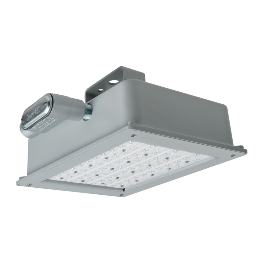
Installation Instructions – Valet LED
Instructions d'installation – Luminaire Valet à DEL
Instrucciones de instalación – de la luminaria LED Valet
Risk of Fire, Electrical Shock, Cuts or other Casualty Hazards- Installation and maintenance of this
product must be performed by a qualified electrician. This product must be installed in accordance
with the applicable installation code by a person familiar with the construction and operation of the
product and hazards involved.
Risk of Fire and Electric Shock- Make certain power is OFF before starting installation or attempting
any maintenance. Disconnect power at fuse or circuit breaker.
Risk of Fire- Refer to product label for specific minimum supply conductor requirements.
Risk of Burn- Disconnect power and allow fixture to cool before handling or servicing.
Risk of Personal Injury- Fixture may become damaged and/or unstable if not installed properly.
Failure to comply with these instructions may result in death, serious bodily injury and property damage.
DISCLAIMER OF LIABILITY: Cooper Lighting Solutions assumes no liability for damages or losses of any kind
that may arise from the improper, careless, or negligent installation, handling or use of this product.
NOTICE: Green ground wire provided in proper location. Do not relocate.
ATTENTION Receiving Department: Note actual fixture description of any shortage or noticeable damage on
delivery receipt. File claim for common carrier (LTL) directly with carrier. Claims for concealed damage must be
filed within 15 days of delivery. All damaged material, complete with original packing must be retained.
Safety: This fixture must be wired in accordance with the National Electrical Code and applicable local codes and
ordinances. Proper grounding is required to insure personal safety. Carefully observe grounding procedure under
installation section.
APPLICATIONS: This lighting fixture is designed for outdoor lighting services, and should not be used in area
of limited ventilation or inside high ambient temperature enclosures. It must be stored in a dry location prior to
installation. Do not expose lighting fixture to rain, dust or other environmental conditions prior to installation
and insertion of photo control or shorting cap (if so equipped). Best results will be obtained if installed and
maintained according to the following recommendations.
WARNING
Brand Logo
reversed out of
Streetworks
black
INS #
INS #
Advertisement
Table of Contents

Related Manuals for Cooper Lighting Streetworks Valet LED


Summary of Contents for Cooper Lighting Streetworks Valet LED
- Page 1 Failure to comply with these instructions may result in death, serious bodily injury and property damage. DISCLAIMER OF LIABILITY: Cooper Lighting Solutions assumes no liability for damages or losses of any kind that may arise from the improper, careless, or negligent installation, handling or use of this product.
-
Page 2: Installation
Connect supply wires to appropriate fixture leads with wire nuts: a) Supply side line voltage wire to black fixture lead. b) Supply side neutral wire to white fixture lead. c) Supply side ground wire to green fixture lead. Cooper Lighting Solutions IB506019EN Installation instructions... - Page 3 [Note – follow all applicable electrical codes for wireway exits – this may require a separate hub [not supplied] to be used at the base of the conduit]. Conduit Nut #2 Figure 4. Cooper Lighting Solutions IB506019EN Installation instructions...
-
Page 4: Tools Required
[latex, silicone, etc.] to seal the joint between the die-cast housing and the mounting surface to avoid water entry through the wire opening in the housing. This particular mounting configuration is rated for ambient usage of 25°C. Cooper Lighting Solutions IB506019EN Installation instructions... - Page 5 Adjust fixture angle orientation then tighten the four bolts on the bracket pivot location. Torque bolts to 15-lbs. CLEARANCE HOLES FOR 5/16” BOLTS (6X) 3.375 [85.73] 2.125 1.123 [53.98] [28.52] 1.063 [26.99] 3.000 [76.20] MOUNTING PATTERN (SCALE 1:2) J-BOX FOR WIRING 45° MAX SCALE 1:4 Cooper Lighting Solutions IB506019EN Installation instructions...
- Page 6 La désobéissance aux instructions suivantes représente un risque de blessures graves ou mortelles et de dommages matériels. EXONÉRATION DE RESPONSABILITÉ : Cooper Lighting Solutions n’assume aucune responsabilité pour les dommages ou pertes de quelque nature que ce soit pouvant découler d’une installation, d’une manipulation ou d’une utilisation inappropriée, imprudente ou négligente de ce produit.
-
Page 7: Outils Requis
Boucle du câble support de montage rapide supérieur, puis fixez-le avec de sécurité deux vis. Crochet du câble Le luminaire est maintenant prêt à la mise sous de sécurité tension. Figure 1. Cooper Lighting Solutions IB506019EN Instructions d’installation... - Page 8 Poussez tous les fils dans la boîte de jonction en vous assurant que toutes les épissures soient dans Le luminaire est maintenant prêt à la mise sous l’enceinte du boîtier d’épissures. tension. Cooper Lighting Solutions IB506019EN Instructions d’installation...
-
Page 9: Entretien
Faites passez les fils dans l’orifice NPT de 3/4 po situé sur le dessus du luminaire. Point de perçage n° 3 Connectez les fils d’alimentation aux fils du luminaire appropriés à l’aide des connecteurs à l’intérieur du Figure 5. Cooper Lighting Solutions IB506019EN Instructions d’installation... - Page 10 TROU DE DÉGAGEMENT POUR BOULON DE 5/16 (6X) 3,375 [85,73] 2,125 1,123 [53,98] [28,52] 1,063 [26,99] 3,000 [76,20] SCHÉMA DE MONTAGE (ÉCHELLE 1:2) BOÎTE DE JONCTION POUR LE CÂBLAGE ANGLE DE 45° MAX ÉCHELLE 1:4 Cooper Lighting Solutions IB506019EN Instructions d’installation...
- Page 11 El incumplimiento de estas instrucciones puede provocar la muerte, lesiones corporales graves y daños materiales. RENUNCIA DE RESPONSABILIDAD: Cooper Lighting Solutions no asume ninguna responsabilidad por daños o pérdidas de ningún tipo que puedan derivarse de la instalación, manipulación o uso incorrecto, descuidado o negligente de este producto.
-
Page 12: Instalación
Ahora puede energizar la luminaria. Herramientas necesarias Destornillador de cabeza Phillips y herramientas para cableado eléctrico. Figura 1. Cooper Lighting Solutions IB506019EN Instrucciones de instalación... - Page 13 8 suministrados. Empuje todos los cables nuevamente hacia el interior de la caja de empalme, asegurándose de que todos Ahora puede energizar la luminaria. Cooper Lighting Solutions IB506019EN Instrucciones de instalación...
-
Page 14: Montaje En Superficie
Pase los cables de alimentación a través de la abertura NPT de 3/4 in en la parte superior de la luminaria. Punto de perforación n.º 3 Conecte los cables de alimentación a los terminales Figura 5. Cooper Lighting Solutions IB506019EN Instrucciones de instalación... - Page 15 ORIFICIO DE PASO PARA PERNOS DE 5/16 IN (6 UNIDADES) 3,375 [85,73] 2,125 1,123 [53,98] [28,52] 1,063 [26,99] 3,000 [76,20] PATRÓN DE MONTAJE (ESCALA 1:2) CAJA DE DERIVACIÓN PARA CABLEADO 45° MÁX. ESCALA 1:4 Cooper Lighting Solutions IB506019EN Instrucciones de instalación...
- Page 16 Garanties et limitation de responsabilité Veuillez consulter le site www.cooperlighting.com pour obtenir les conditions générales. Garantías y Limitación de Responsabilidad Visite www.cooperlighting.com para conocer nuestros términos y condiciones. Cooper Lighting Solutions is a registered trademark. All trademarks are property Cooper Lighting Solutions of their respective owners.
Need help?
Do you have a question about the Streetworks Valet LED and is the answer not in the manual?
Questions and answers