Advertisement
Available languages
Available languages
Quick Links
IB516001EN
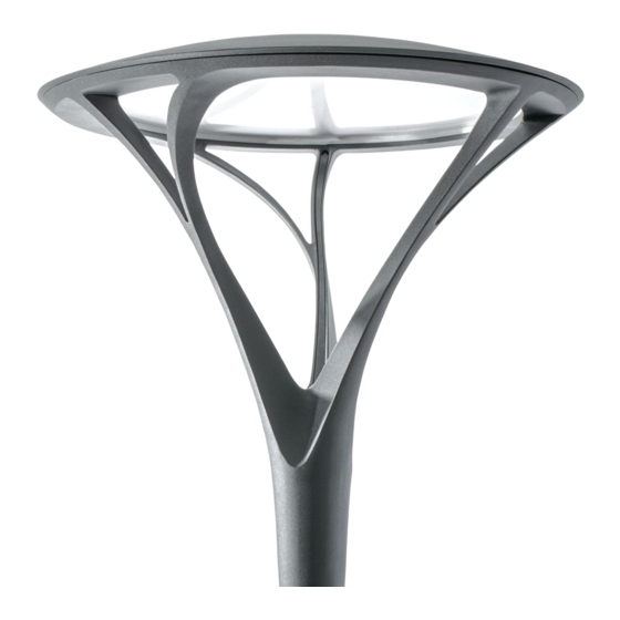
Installation Instructions – Arbor Post Top
Instructions d'installation – Haut de poteau Arbor
Instrucciones de instalación – Luminaria para poste de rotonda
WARNING
Customer is responsible for engineering analysis
to confirm pole and fixture compatibility for all
applications. Serious bodily injury or property damage
may occur if the pole mounted luminaire is not
installed to a compatible new or existing pole specific
to the conditions of your installation and physical
location. Refer to our pole white paper WP513001EN
for additional support information.
WARNING
Make certain power is OFF before starting installation
or attempting any maintenance.
WARNING
Risk of fire/electric shock. If not qualified, consult an
electrician.
WARNING
Risk of Electric Shock – Disconnect power at fuse or
circuit breaker before installing or servicing.
WARNING
Risk of Burn – Disconnect power and allow fixture to
cool before servicing.
IMPORTANTe: Read carefully before installing fixture. Retain for future reference.
GENERALe: Upon receipt of the fixture, thoroughly inspect for any freight damage which should be brought to the
attention of the delivery carrier. Compare the catalog description listed on the packing slip with the fixture label on the
housing to assure you have received the correct material.
SAFETYe: This fixture must be wired in accordance with the National Electrical Code and applicable local codes and
ordinances. Proper grounding is required to insure personal safety. Carefully observe grounding procedure under
installation section.
APPLICATIONSe: This lighting fixture is designed for outdoor lighting services, and should not be used in area of limited
ventilation or inside high ambient temperature enclosures. It must be stored in a dry location prior to installation. Do
not expose lighting fixture to rain, dust or other environmental conditions prior to installation and insertion of photo
control or shorting cap (if so equipped). Do not install the fixture near combustible materials or locate next to airflow
blocking surfaces within 6 inches. Best results will be obtained if installed and maintained according to the following
recommendations.
WARNING
Risk of Personal Injury – Fixture may become damaged
and/or unstable if not installed properly.
Do not mount luminaire within 6" of a
●
●
combustible surface.
Do not handle luminaire by the glass. Do not
●
●
touch LEDs.
N
otee:
These instructions do not claim to cover all
details or variations in the equipment, procedure,
or process described, nor to provide directions
for meeting every possible contingency during
installation, operation or maintenance. When
additional information is desired to satisfy a
problem not covered sufficiently for user's purpose,
please contact your nearest representative.
N
otee:
This lighting fixture has been shipped complete
with one of several mounting options. Please follow
the installation instructions specific to the catalog
part that you ordered.
N
otee:
Care must be taken not to set lighting fixture down
on optical lenses or lift the fixture in the lens area.
N
otee:
Specifications and dimensions subject to change
without notice.
Brand Logo
reversed out of
black
INS #
INS #
Advertisement

Related Manuals for Cooper Lighting Arbor Post Top


Summary of Contents for Cooper Lighting Arbor Post Top
- Page 1 Brand Logo reversed out of black IB516001EN INS # INS # Installation Instructions – Arbor Post Top Instructions d’installation – Haut de poteau Arbor Instrucciones de instalación – Luminaria para poste de rotonda WARNING WARNING Customer is responsible for engineering analysis Risk of Personal Injury –...
-
Page 2: Installation
Installation Instructions – Arbor Post Top INSTALLATION This lighting fixture has been shipped complete with one of several mounting options. Please follow the installation instructions specific to the catalog part that you ordered. otee: Care must be taken not to set lighting fixture down on optical lenses or lift the fixture in the lens area. - Page 3 Installation Instructions – Arbor Post Top B. Pole Mount Single Arm (4" or 5" O.D. Pole with 2-3/8" or 3" O.D. Tenon. Tenon Length Range 4" to 6" Single Support Arm Only) If using pole with 2-3/8" tenon, slipfit the spacer provided onto the tenon of the pole.
- Page 4 Installation Instructions – Arbor Post Top C. Post Mount Twin Arm (4" or 5" O.D. Pole; 3" O.D. 12. Connect supply wires to appropriate luminaire leads (Figure 9.) Tenon Only, Tenon Length Range 4" to 6" Only) Loosen and take off the two caps from twin arm.
- Page 5 Installation Instructions – Arbor Post Top For luminaire with asymmetric optics, rotate the fixtures according to arrow mark on the dome towards the street side. (Figure 12.) Use one of the two bottom most holes on the luminaires as a template to drill a pilot hole into the...
- Page 6 Installation Instructions – Arbor Post Top 10. Once connections are completely made, carefully push Supply Wires all the wires back into the arm’s hole where the cap was removed from. Tighten the caps to close twin arm’s holes. (Figure 15.) otee: Make sure wires do not get pinched.
-
Page 7: Wall Mount
Installation Instructions – Arbor Post Top For luminaire with asymmetric optics, rotate the fixture according to arrow mark on the dome towards the Flat Washer street side. (Figure 18.) Wall Install six 3/8-24 x3/8” set screws to hold the luminaire Lock Washer on arm tenon and tighten to 160 inch-lbs. - Page 8 Installation Instructions – Arbor Post Top Pull the leads from luminaire through the tenon and cap hole. (Figure 21.) Three Leads from Fixture Slip fit the luminaire on the tenon of wall-mount arm. otee: Make sure the wires do not get pinched.
- Page 9 N'installez pas le luminaire près de matériaux combustibles et ne le placez pas à proximité de surfaces bloquant la circulation de l'air dans un rayon de 15,2cm (6po). Les résultats seront meilleurs si le luminaire est installé et entretenu selon les recommandations suivantes. COOPER LIGHTING SOLUTIONS IB516001EN Instructions d’installation...
-
Page 10: Outillage Nécessaire
(0,375po) et serrez-les selon un couple de 18,01N-m (160po-lb). (Figure 4.) (6) Vis (6) Vis de à écrou fixation Blanc Fil neutre Ligne de Noir voltage Fil de mise à la terre Vert Figure 4. Figure 1. COOPER LIGHTING SOLUTIONS IB516001EN Instructions d’installation... - Page 11 Trois fils capuchon. (Figure 7 .) 10. Insérez le luminaire dans le tenon du bras unique en le faisant glisser. Vérifiez que les fils ne sont pas coincés. emarquee: Figure 7. COOPER LIGHTING SOLUTIONS IB516001EN Instructions d’installation...
- Page 12 Insérez le bras double dans le tenon du poteau et tournez le bras double dans la position souhaitée. Vérifiez que les fils d'alimentation ne sont emarquee: Bras double pas coincés. Tenon de poteau Figure 10. COOPER LIGHTING SOLUTIONS IB516001EN Instructions d’installation...
- Page 13 Percez un trou de 4,76mm Percez (3/16po) et l'avant-trouà taraudez à l'aide du Détail 2: Percez à 1/4-20po canon de 4,76mm (3/16po) perçage et taraudez à Détail 1: Perçage 1/4-20po de l'avant-trou Figure 13. COOPER LIGHTING SOLUTIONS IB516001EN Instructions d’installation...
- Page 14 2,22cm (3/4po) si la taille du tenon est de 5,83cm (2-3/8po). Utilisez des vis Tenon de poteau d'ajustement de 1,27 cm (3/8 po) si la taille du tenon est de 7 ,62 cm (3 po). Figure 16. COOPER LIGHTING SOLUTIONS IB516001EN Instructions d’installation...
-
Page 15: Montage Mural
(3/16 po) et serrez-les selon un couple de 18,01 N-m (160 po-lb). Montage Fils mural de MISE EN GARDE d'alimentation support Joint unique Un serrage excessif des vis peut endommager le luminaire. Figure 19. COOPER LIGHTING SOLUTIONS IB516001EN Instructions d’installation... - Page 16 Le fil neutre provenant de l'alimentation avec le fil ● ● blanc du luminaire. Le fil de tension provenant de l'alimentation avec le ● ● fil noir du luminaire. COOPER LIGHTING SOLUTIONS IB516001EN Instructions d’installation...
- Page 17 14. Installez six vis à écrou de 3/8-24 po x 4,76 mm sur le dôme (3/16po) et serrez-les selon un couple de 18,01 N-m (160 po-lb). Côté rue MISE EN GARDE Figure 23. Un serrage excessif des vis peut endommager le luminaire. COOPER LIGHTING SOLUTIONS IB516001EN Instructions d’installation...
- Page 18 No instale la luminaria cerca de materiales combustibles ni la ubique junto a superficies de bloqueo de flujo de aire a menos de 6 pulgadas (15.24 cm). Obtendrá mejores resultados si la mantiene e instala conforme a las siguientes recomendaciones. COOPER LIGHTING SOLUTIONS IB516001EN Instrucciones de instalación...
-
Page 19: Instalación
Instale seis tornillos de bloqueo de 3/8-24 x 0.1875" y ajústelos hasta 160 in-lb. (Figura 4.) (6) Tornillos (6) Tornillos de bloqueo de sujeción Cable neutro Blanco Cable de voltaje de línea Negro Cable de conexión a Verde tierra Figura 4. Figura 1. COOPER LIGHTING SOLUTIONS IB516001EN Instrucciones de instalación... - Page 20 Asegúrese de que los cables no queden apretados. Brazo de soporte individual Tres cables de alimentación Tapón Marca de flecha en el domo Espiga del poste LADO DE LA CALLE Lado de la calle Figura 5. Figura 8. COOPER LIGHTING SOLUTIONS IB516001EN Instrucciones de instalación...
- Page 21 Figura 11. PRECAUCIÓN Si se sobreajustan los tornillos, se puede dañar la luminaria. Dirija las luminarias a las espigas de dos brazos a ambos lados. otae: Asegúrese de que los cables no queden apretados. COOPER LIGHTING SOLUTIONS IB516001EN Instrucciones de instalación...
- Page 22 Detalle 2: Detalle 1: Orificio casquillo del Orificio de 3/16 de perforación taladro y tapa de 1/4-20 piloto Figura 13. Luminaria Luminaria Marca de flecha en el domo Poste Figura 14. Figura 12. COOPER LIGHTING SOLUTIONS IB516001EN Instrucciones de instalación...
- Page 23 3/8" si el tamaño de la espiga es de 3". PRECAUCIÓN Cables de alimentación Si se sobreajustan los tornillos, se puede dañar la luminaria. Adaptador de la espiga Luminaria Luminaria Brazo doble Tapón Espiga del poste Figura 16. Tapón Figura 15. COOPER LIGHTING SOLUTIONS IB516001EN Instrucciones de instalación...
- Page 24 Instale seis tornillos de bloqueo de 3/8-24 x 3/16" y ajústelos hasta 160 in-lb. PRECAUCIÓN Si se sobreajustan los tornillos, se puede dañar la luminaria. Soporte de montaje en Cables de pared con alimentación Junta sostén individual Figura 19. COOPER LIGHTING SOLUTIONS IB516001EN Instrucciones de instalación...
- Page 25 El cable neutro del lado de la alimentación con el ● ● terminal blanco de la luminaria. El cable de tensión de línea del lado de la ● ● alimentación con el terminal negro de la luminaria. COOPER LIGHTING SOLUTIONS IB516001EN Instrucciones de instalación...
- Page 26 14. Instale seis tornillos de bloqueo de 3/8-24 x 3/16" y Lado de la calle ajústelos hasta 160 in-lb. PRECAUCIÓN Figura 23. Si se sobreajustan los tornillos, se puede dañar la luminaria. COOPER LIGHTING SOLUTIONS IB516001EN Instrucciones de instalación...
- Page 28 Garanties et limitation de responsabilité Veuillez consulter le site www.cooperlighting.com pour obtenir les conditions générales. Garantías y Limitación de Responsabilidad Visite www.cooperlighting.com para conocer nuestros términos y condiciones. Cooper Lighting Solutions is a registered trademark. Cooper Lighting Solutions All trademarks are property 1121 Highway 74 South of their respective owners.
Need help?
Do you have a question about the Arbor Post Top and is the answer not in the manual?
Questions and answers