Table of Contents
Advertisement
Quick Links
Thank you for purchasing a Sealey product. Manufactured to a high standard, this product will, if used according to these instructions,
and properly maintained, give you years of trouble free performance.
IMPORTANT: PLEASE READ THESE INSTRUCTIONS CAREFULLY. NOTE THE SAFE OPERATIONAL REQUIREMENTS, WARNINGS & CAUTIONS. USE
THE PRODUCT CORRECTLY AND WITH CARE FOR THE PURPOSE FOR WHICH IT IS INTENDED. FAILURE TO DO SO MAY CAUSE DAMAGE AND/OR
PERSONAL INJURY AND WILL INVALIDATE THE WARRANTY. KEEP THESE INSTRUCTIONS SAFE FOR FUTURE USE.
Refer to
Wear eye
instruction
protection
manual
1. SAFETY
WARNING! Ensure health & safety, local authority, and general workshop practice regulations are strictly adhered to when using this
‰
equipment.
Familiarise yourself with product application and limitations, as well as the specific potential hazards peculiar to this product.
9
Maintain the meter in good condition (use an authorised service agent).
9
Replace or repair damaged parts. Use genuine parts only. Non authorised parts will invalidate the warranty.
9
Use only to meter diesel fuel and oils.
9
Ensure safety eye protection and protective clothing are worn when using this product.
9
Keep the work area clean, uncluttered and ensure there is adequate lighting.
9
Maintain correct balance and footing. Ensure the floor is not slippery and wear non slip shoes.
9
Keep children and unauthorised persons away from the working area.
9
After use, drain any fluids from the equipment before storage.
9
Dispose of waste liquids in accordance with local authority regulations.
9
dO NOT exceed the maximum pressure of 145psi (10bar).
8
dO NOT use the equipment near open flames.
8
dO NOT smoke whilst using this equipment.
8
dO NOT use for corrosive fluids.
8
dO NOT dismantle, tamper with or adapt the equipment for any purpose other than for which it is designed.
8
dO NOT use the unit if it has been dropped or mishandled, check the unit to ensure there is no damage.
8
dO NOT use taper connections, use parallel connectors only.
8
dO NOT use compressed air on the turbine, the excessive rotation will damage the unit.
8
Keep the meter clean and store in a safe dry, childproof location.
9
WARNING! dO NOT allow uncontrolled discharge of fluids thus polluting the environment. All liquids must be disposed of according to
‰
local authority regulations.
WARNING! The correct working of the nutating disk may be affected if solid particles enter the measuring chamber. Always filter the
‰
fluid by installing a filter on the meter inlet.
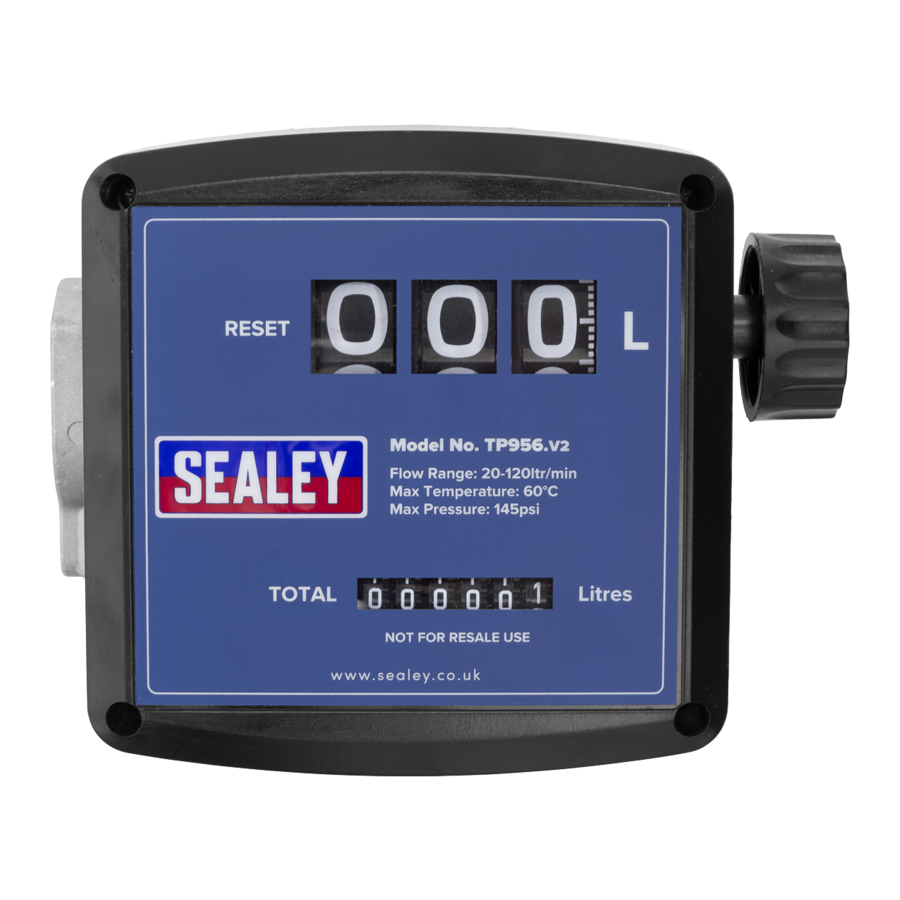
2. INTROdUcTION
Volumetric nutating disc meter with three digit resettable batch display and six digit cumulative total display. Unique filter and flange
assembly allows meter to be positioned in four configurations. Suitable replacement meter for Model no. TP955 Diesel/Fluid
Transfer System.
3. SPEcIFIcATION
Model No. ............................................................... TP956.V2
Flow Rate .......................................................... 20-120ltr/min
Weight ........................................................................... 1.8kg
Max. Working Pressure ................................... 145psi (10bar)
4. INSTALLATION
NOTE: Numbers refer to Parts Diagram section 9.
4.1.
The meter can be installed in any position, on rigid pipelines or flexible
hoses, directly on pumps or tanks. The meter flow direction is fixed and
indicated by an arrow on the outlet.
4.2.
Meter cover (3) can be removed and the Register base (8), along with
Meter Unit (6), can be rotated at every 90° orientation in four different
positions.
NOTE: The rear of the meter body is equipped with 4 blind holes which
can be threaded (M5) for a mounting.
4.3.
HOW TO ROTATE THE dISPLAY
4.3.1.
Remove the four retaining screws (5) and lift up the meter cover (3), fig.1.
4.3.2.
Loosen the 2 screws, see fig.2, on both sides and separate the meter unit (6) from the register base (8).
© Jack Sealey Limited
dIESEL & FLUId FLOW METER
MODEL NO:
Wear protective
clothing
Original Language Version
TP956.V2
fig.1
TP956.V2 | Issue:1 15/10/18
Advertisement
Table of Contents

Related Manuals for Sealey TP956.V2


Summary of Contents for Sealey TP956.V2
- Page 1 TP956.V2 MODEL NO: Thank you for purchasing a Sealey product. Manufactured to a high standard, this product will, if used according to these instructions, and properly maintained, give you years of trouble free performance. IMPORTANT: PLEASE READ THESE INSTRUCTIONS CAREFULLY. NOTE THE SAFE OPERATIONAL REQUIREMENTS, WARNINGS & CAUTIONS. USE THE PRODUCT CORRECTLY AND WITH CARE FOR THE PURPOSE FOR WHICH IT IS INTENDED.
- Page 2 WARNING! Before disassembling always make sure the line pressure is released and all fluid is drained from the meter. ‰ 7.1. The meter does not require any special maintenance other than cleaning of the measuring chamber, (it may get clogged due to insufficient filtration). Original Language Version © Jack Sealey Limited TP956.V2 | Issue:1 15/10/18...
- Page 3 Air in the fluid Locate and eliminate leaks in inlet lines Reduced flow rate Clogged measuring chamber Clean measuring chamber, see section 7.2 Blocked or soiled filter Clean the filter TP956.V2 | Issue:1 15/10/18 Original Language Version © Jack Sealey Limited...
- Page 4 16 Calibration screw + O ring 17 Plug + seal Parts support is available for this product. Please email sales@sealey.co.uk or telephone 01284 757500 ENVIRONMENT PROTEcTION Recycle unwanted materials instead of disposing of them as waste. All tools, accessories and packaging should be sorted, taken to a recycling centre and disposed of in a manner which is compatible with the environment.
Need help?
Do you have a question about the TP956.V2 and is the answer not in the manual?
Questions and answers