Table of Contents
Advertisement
Advertisement
Table of Contents

Related Manuals for Sealey TA320


Summary of Contents for Sealey TA320
- Page 1 User's Guide True RMS Industrial Multimeter...
- Page 3 Introduction This meter measures AC/DC Voltage, AC/DC Current, Resistance, Capacitance, Frequency (electrical & electronic), Duty Cycle, Diode Test,Insulation Test, and Continuity plus Thermocouple Temperature. It can store and recall data. It features a waterproof, rugged design for heavy duty use. Proper use and care of this meter will provide many years of reliable service.
- Page 4 PER IEC1010 OVERVOLTAGE INSTALLATION CATEGORY OVERVOLTAGE CATEGORY I Equipment of OVERVOLTAGE CATEGORY I is equipment for connection to circuits in which measures are taken to limit the transient overvoltages to an appropriate low level. Note – Examples include protected electronic circuits. OVERVOLTAGE CATEGORY II Equipment of OVERVOLTAGE CATEGORY II is energy-consuming equipment to be supplied from the fixed installation.
-
Page 5: Safety Instructions
SAFETY INSTRUCTIONS This meter has been designed for safe use, but must be operated with caution. The rules listed below must be carefully followed for safe operation. NEVER apply voltage or current to the meter that exceeds the specified maximum: Input Protection Limits Function Maximum Input... - Page 6 ALWAYS turn off the power and disconnect the test leads before opening the covers to replace the fuse or batteries. NEVER operate the meter unless the back cover and the battery and fuse covers are in place and fastened securely. If the equipment is used in a manner not specified by the manufacturer, the protection provided by the equipment may be impaired.
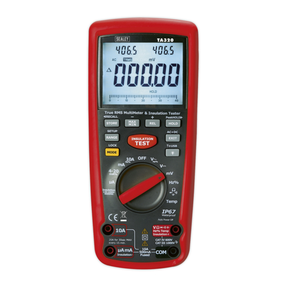
- Page 7 Symbols and Annunciators •))) Continuity Diode test Battery status nano (10 ) (capacitance) µ micro (10 ) (amps, cap) milli (10 ) (volts, amps) Amps kilo (10 ) (ohms) Farads (capacitance) mega (10 ) (ohms) Ohms PEAK Peak Hold Ω Hertz (frequency) Volts Percent (duty ratio)
-
Page 8: Dc Voltage Measurements
Operating Instructions WARNING: Risk of electrocution. High-voltage circuits, both AC and DC, are very dangerous and should be measured with great care. 1. ALWAYS turn the function switch to the OFF position when the meter is not in use. 2. If “OL” appears in the display during a measurement, the value exceeds the range you have selected. -
Page 9: Ac Voltage (Frequency, Duty Cycle) Measurements
AC VOLTAGE (FREQUENCY, DUTY CYCLE) MEASUREMENTS WARNING: Risk of Electrocution. The probe tips may not be long enough to contact the live parts inside some 240V outlets for appliances because the contacts are recessed deep in the outlets. As a result, the reading may show 0 volts when the outlet actually has voltage on it. -
Page 10: Mv Voltage Measurements
MV VOLTAGE MEASUREMENTS CAUTION: Do not measure mV voltages if a motor on the circuit is being switched ON or OFF. Large voltage surges may occur that can damage the meter. 1. Set the function switch to the green mV position. 2. -
Page 11: Dc Current Measurements
DC CURRENT MEASUREMENTS CAUTION: Do not make 20A current measurements for longer than 30 seconds. Exceeding 30 seconds may cause damage to the meter and/or the test leads. 1. Insert the black test lead banana plug into the negative COM jack. 2. -
Page 12: Ac Current (Frequency, Duty Cycle) Measurements
AC CURRENT (FREQUENCY, DUTY CYCLE) MEASUREMENTS CAUTION: Do not make 20A current measurements for longer than 30 seconds. Exceeding 30 seconds may cause damage to the meter and/or the test leads. Insert the black test lead banana plug into the negative COM jack. For current measurements up to 4000µA AC, set the function switch to the yellow µA position and insert the... -
Page 13: Resistance Measurements
14. Press and hold the MODE button to return to current measurement. 15. Press EXIT for 2 seconds into the function of AC+DC. Test DC and AC TURE Rms. RESISTANCE MEASUREMENTS WARNING: To avoid electric shock, disconnect power to the unit under test and discharge all capacitors before taking any resistance measurements. -
Page 14: Continuity Check
CONTINUITY CHECK WARNING: To avoid electric shock, never measure continuity on circuits or wires that have voltage on them. 1. Set the function switch to the green Ω CAP position. 2. Insert the black lead banana plug into the negative COM jack. Insert the red test lead banana plug into the positive Ω... -
Page 15: Capacitance Measurements
CAPACITANCE MEASUREMENTS WARNING: To avoid electric shock, disconnect power to the unit under test and discharge all capacitors before taking any capacitance measurements. Remove the batteries and unplug the line cords. 1. Set the rotary function switch to the green Ω... -
Page 16: Frequency (Duty Cycle) Measurements (Electronic)
FREQUENCY (DUTY CYCLE) MEASUREMENTS (ELECTRONIC) 1. Set the rotary function switch to the green Hz/% position. 2. Insert the black lead banana plug into the negative COM jack and the red test lead banana plug into the positive Hz jack. 3. - Page 17 phase with analog bar; on the top right corner display, the tested insulation voltage in V (DC) is indicated, the symbol “ ” flashes and the buzzer warns frequently d)Being free from the “TEST” button or pushing down the “TEST” button in the “LOCK “...
- Page 18 individually. If the motor is disconnected at the motor terminals, connect one megohmmeter lead to the grounded motor housing and the other lead to One of the motor leads. DC-Disconnect the motor from the line. To test the brush rigging,field coils and armature connect one megohmmeter lead to the grounded motor housing and the other lead to the brush on the commutator.
- Page 19 CABLES Disconnect the cable from the line. Also disconnect opposite end to avoid errors due to leakage from other equipment. Check each conductor to ground and /or lead sheath by connecting one megohmmeter lead to a ground and /or lead sheather and the other megohmmeter lead to each of the conductors in turn.
-
Page 20: Autoranging/Manual Range Selection
AUTORANGING/MANUAL RANGE SELECTION When the meter is first turned on, it automatically goes into AutoRanging. This automatically selects the best range for the measurements being made and is generally the best mode for most measurements. For measurement situations requiring that a range be manually selected, perform the following: 1. - Page 21 3. Left auxiliary display display the margin of initial value and the current value. Right auxiliary display display the initial reading. Main display the reading after REL TEST. 4. Press the EXIT button to exit the relative mode. Display Backlight Press the key to turn the backlight on.
- Page 22 Press STORE button again, enter into recording interval time set up function. On the left upper shows 0000 S ,which states recording interval time; using button + & - to select,the range is 0~255 seconds。 When the recording interval time is 0000 S,then press STORE button again to change into manual recording.
-
Page 23: Low Battery Indication
C: auto power off time D: turn off phonating E: back lit time Use ←、+、-、→ buttons to select the parameter Press SET button continuously to switch to setting content, till exiting set up to testing mode. So the updated setting content is saved. -
Page 24: Battery Installation
3. HANDLE THE METER GENTLY AND CAREFULLY. Dropping it can damage the electronic parts or the case. 4. KEEP THE METER CLEAN. Wipe the case occasionally with a damp cloth. DO NOT use chemicals, cleaning solvents, or detergents. 5. USE ONLY FRESH BATTERIES OF THE RECOMMENDED SIZE AND TYPE. -
Page 25: Replacing The Fuses
REPLACING THE FUSES WARNING: To avoid electric shock, disconnect the test leads from any source of voltage before removing the meter cover. 1. Disconnect the test leads from the meter. 2. Remove the protective rubber holster. 3. Remove the battery cover (two “B” screws) and the battery. 4. - Page 26 Specifications Function Range Resolution Accuracy DC Voltage 400mV 0.01mV 0.0001V ± (0.06% reading + 4digits) 0.001V 400V 0.01V 1000V 0.1V ± (0.1% reading + 5digits) AC Voltage 50 to 1000Hz 400mV 0.1mV ± (1.0% reading + 7digits) 0.001V 0.01V 400V 0.1V ±...
- Page 27 (20A: 30 sec max with reduced accuracy) AC Current 50 to 1000Hz (AC+DC) 400µA 0.1µA 4000µA 1µA 40mA 0.01mA ± (1.5% reading + 7digits) 400mA 0.1mA 0.01A AC+DCCurren 400µA 0.1µA ± (1.5% reading + 7digits) 4000µA 1µA 40mA 0.01mA 400mA 0.1mA 0.01A (20A: 30 sec max with reduced accuracy)
- Page 28 Function Range Resolution Accuracy Resistance 400Ω 0.01Ω ± (0.3% reading + 9 digits) 4kΩ 0.0001kΩ 40kΩ 0.001kΩ ± (0.3% reading + 4 digits) 400kΩ 0.01kΩ 4MΩ 0.001MΩ 40MΩ 0.001MΩ ± (2.0% reading + 10 digits) Capacitance 40nF 0.001nF ± (3.5% reading + 40 digits) 400nF 0.01nF 4µF...
- Page 29 (type-K) -58 to 1832°F 0.1°F ±(1.0% reading +4.5°F) (probe accuracy not included) 4-20mA% -25 to 125% 0.01% ±50 digits 0mA=-25%, 4mA=0%, 20mA=100%, 24mA=125% Meg OHMS Test Short Termina Range Resoluti Accuracy Current circuit current Voltage 125V(0 0.125~4.000 M Ω 0.001M Ω...
- Page 30 Note: Accuracy specifications consist of two elements: • (% reading) – This is the accuracy of the measurement circuit. • (+ digits) – This is the accuracy of the analog to digital converter. Store capacitance 2000 Enclosure Double molded, waterproof Shock (Drop Test) 6.5 feet (2 meters) Diode Test...
- Page 31 Polarity Automatic (no indication for positive); Minus (-) sign for negative Measurement Rate 2 times per second, nominal Low Battery Indication “ ” is displayed if battery voltage drops below operating voltage Battery One 9 volt (NEDA 1604) battery Fuses mA, µA ranges;...
Need help?
Do you have a question about the TA320 and is the answer not in the manual?
Questions and answers