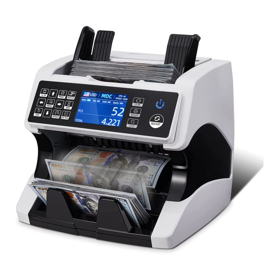
MUNBYN IMC01 Maintenance Manual
Hide thumbs
Also See for IMC01:
- User manual (41 pages) ,
- Frequently asked questions manual (18 pages) ,
- Maintenance manual (15 pages)
Summary of Contents for MUNBYN IMC01
- Page 1 IMC01 Banknote Counter Maintenance Manual 1.03 Document Name: IMC01 Maintenance Manual-1.03.docx Name Signature Date Prepared by: Byron Zhong Reviewed by: Approved by:...
-
Page 2: Version History
1.01 • Add the detail description of screw tuning 2020-11-23 Byron Zhong 1.02 • Add some pictures for CIS calibration • Add the section of “Back to Default Setting” 2021-1-12 Byron Zhong 1.03 • Page2of18 IMC01 Maintenance Manual Version 1.03... -
Page 3: Table Of Contents
Back to Default Setting....................16 4.4. Sensors Replacement ..................... 17 4.4.1. Hopper Sensor ....................... 17 4.4.2. Stacker Sensor ....................... 17 4.4.3. Counting Sensor ..................... 17 4.5. Power Board Replacement ..................... 17 4.6. Mainboard Replacement ....................17 Page3of18 IMC01 Maintenance Manual Version 1.03... -
Page 4: Overview
1.0. Overview Thank you for purchasing our banknote counters IMC01. After starting the machine, it will go on self-check automatically. If the preset window shows the error code or tell you to clean the sensors, generally speaking, it is because of dust on the surface or sensor blocked by notes. -
Page 5: Cleaning The Machine
As shown in the following figure, clean the banknote processing wheel with nylon brush or cleaning cloth. Banknote Banknote Processing Processing Wheel Wheel Figure 2-2 Banknote Processing Wheel 3) Banknote entrance As shown in the following figure, clean the banknote entrance with nylon brush. Page5of18 IMC01 Maintenance Manual Version 1.03... -
Page 6: Clean The Stacker Sensors
Figure 2-3 Banknote Entrance 2.2. Clean the Stacker Sensors As shown in the following figure, clean the stacker sensors with nylon brush or cleaning cloth. Stacker Sensor Stacker Sensor Figure 2-4 Stacker Sensors Page6of18 IMC01 Maintenance Manual Version 1.03... -
Page 7: Clean The Internal Sensors
2) Pull the handle of internal back covering the direction shown in Figure 2-5 to open it. The Handle of External Back Cover Figure 2-7 Handle of Internal Back Cover 3) Clean the lower CIS and Lower UV sensors with cleaning cloth or nylon brush respectively. Page7of18 IMC01 Maintenance Manual Version 1.03... - Page 8 Figure 2-8 Lower Sensors 4) Clean the upper CIS with cleaning cloth. Upper CIS Figure 2-9 Upper CIS Sensor Note: For the CIS sensors, it is recommended to used cleaning cloth to clean them. Page8of18 IMC01 Maintenance Manual Version 1.03...
-
Page 9: Error Analysis
IR reflect area 1 error In the process of using the IMC01, the IMC01 may show abnormal state and display the error codes on the screen. The description of the error codes and the related handling method is shown in table 3-1. -
Page 10: Bill Jam
The IMC01 banknote counter will take a few seconds to conduct a self-check with spinning the counting wheels after power on. The IMC01 will check the sensors, the following errors may happen if the sensors have been blocked or damaged. -
Page 11: Stacker Sensor Error
If the number of banknote counting is always not correct, or the “Main Motor Error” is shown on the screen, that means the counting sensor error doesn’t work. Please clean the machine first. If the error still happens, please follow the instruction of the counting sensor error maintenance according to section 4.3.3. Page11of18 IMC01 Maintenance Manual Version 1.03... -
Page 12: Maintenance
In order to fine tune the screw, please stop the auto counting first, and insert one banknote to the gap between the rollers to check if the banknote can be inserted smoothly, as shown in the following. Page12of18 IMC01 Maintenance Manual Version 1.03... -
Page 13: Cis Calibration
CIS calibration is needed when there are many errors during the banknote counting process. 1) Please enter the menu interface. And go to the service menu with the password “9999”, as shown in the following figures. Page13of18 IMC01 Maintenance Manual Version 1.03... - Page 14 Figure 4-8 Service Menu 2) Click the “CIS Calibration” option, the screen will be shown in the following figure. Figure 4-9 CIS Calibration Interface 3) Open the back cover to clean the CIS sensors with cleaning cloth. Page14of18 IMC01 Maintenance Manual Version 1.03...
- Page 15 Figure 4-12 Clean the Upper CIS 4) Put the CIS calibration paper (white paper) inside, and close the back covers. Figure 4-13 Place the CIS Calibration Paper 5) Start CIS calibration by pressing the “RESTART” button. Page15of18 IMC01 Maintenance Manual Version 1.03...
-
Page 16: Back To Default Setting
2) As shown in above figure, choose “⑩. Back to Default Setting” and enter the menu key. It will enter to the following display on the screen. Figure 4-16 Default Setting Interface 3) Press the RESTART key, the IMC01 will reset all the changed settings before. Figure 4-17 Default Setting Guide Page16of18 IMC01 Maintenance Manual Version 1.03... -
Page 17: Sensors Replacement
4) Go back the main screen, and the use your finger to touch the hopper sensor. The processing wheels and rollers in the IMC01 will run for a while. Figure 4-18 Touch the Hopper Sensor 4.4. Sensors Replacement 4.4.1. Hopper Sensor Please contact and return to us for repairment. - Page 18 Scan the QR code for Facebook online chat Contact us OUTLOOK: munbyn@outlook.com Whatsapp: +86-17817881067 If you meet any problem during using the IMC01, please contact us. Page18of18 IMC01 Maintenance Manual Version 1.03...


Need help?
Do you have a question about the IMC01 and is the answer not in the manual?
Questions and answers