Table of Contents
Advertisement
Advertisement
Table of Contents

Subscribe to Our Youtube Channel
Related Manuals for RBSM Viper


Summary of Contents for RBSM Viper
- Page 2 Dear Customer In purchasing this bicycle you have chosen a product of high quality and technology. Each com- ponent of your new bicycle has been designed, manufactured and assembled with great care and expertise. These operating instructions contain a wealth of information on the proper use of your bicycle, its maintenance and operation as well as interesting information on bicycle design and engineer- ing.
-
Page 3: Table Of Contents
Content The bike and its components ..................5 SAFETY WARNINGS ..................7 I-1. Basic safety information .................7 I-2. For your own safety ..................7 I-3. Jnformation for parents and legal guardians ..........7 I-4. Safety in road traffic ..................7 I-5. Bike safety .....................8 Quick Start Guide: ..................9 III. - Page 4 XIV-5. Features .......................26 XIV-6. General Operation ..................27 XIV-7. Settings ......................31 XIV-8. Quality Assurance and Warranty Scope ............34 XIV-9. Operation Cautions ..................35 Assistance by the electric motor .............36 XV-1. Operating principle of assistance ..............36 XV-2. Distance .......................36 XVI. Battery ......................36 XVI-1. Straightforward charging ................37 XVI-2.
-
Page 5: The Bike And Its Components
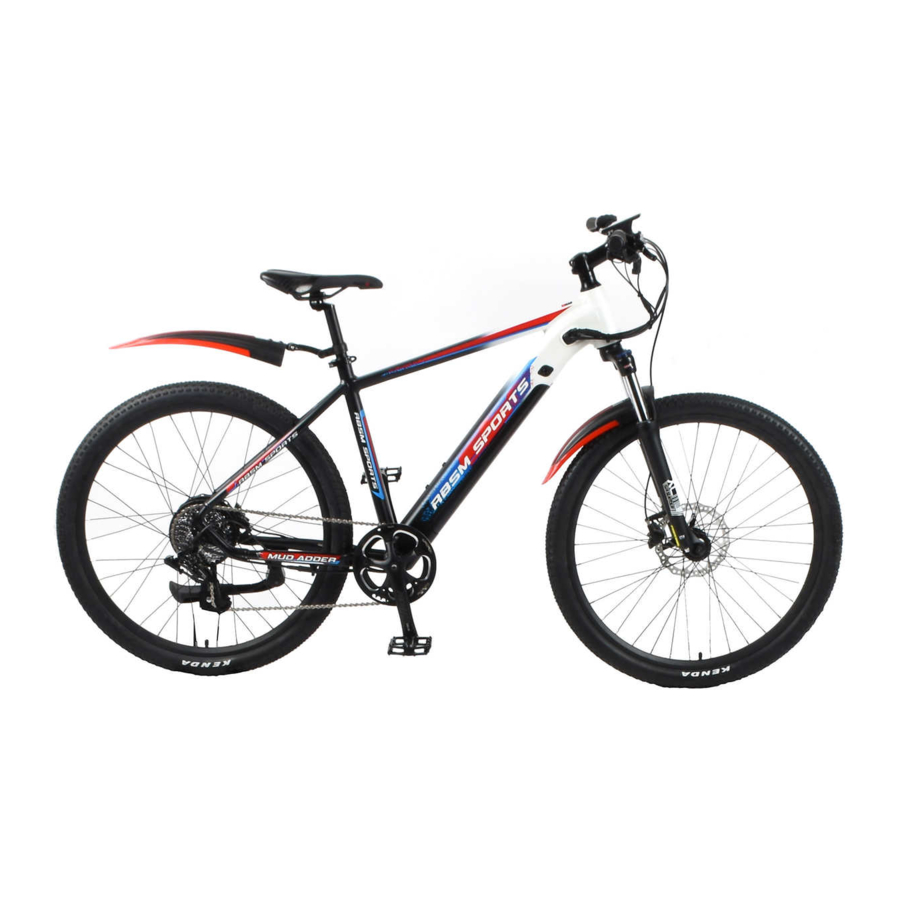
The bike and its components Mud Adder Whole Vehicle Mark 1. Tire 2. Rim 3. Spoke 4. Front fork 5. Stem 6. Saddle post clamp 7. Saddle post 8. Saddle 9. Battery 10. Flywheel 11. Derailleur 12. Chain 13. Crank 14. - Page 6 Viper Whole Vehicle Mark 1. Tire 2. Rim 3. Spoke 4. Front fork 5. Stem 6. Saddle post clamp 7. Saddle post 8. Saddle 9. Battery 10. Flywheel 11. Derailleur 12. Chain 13. Crank 14. Pedal 15. Disc Brake 16. Handle bar 17.
-
Page 7: Safety Warnings
Preface Keep in mind that every bicycle type is built for a specific intended use. Be sure to use your bi- cycle only according to its intended use, as it may otherwise not withstand the stress and would fail and cause an accident with unforeseeable consequences! 1. -
Page 8: Bike Safety
regulations. • Adjust your handling on wet or slippery roads; ride more slowly and brake carefully and in good time as you will require a much greater braking distance. • Adopt a speed that reflects the terrain as well as your riding ability. • Do not listen to music through headphones when cycling. • Do not cycle when using a mobile phone. -
Page 9: Quick Start Guide
Quick Start Guide: 8 steps to getting on the road (Before the first ride) CAUTION: E-BIKE OWNERS: Do not use the battery for the first time until it has been fully charged at least once or you may decrease its perform¬ance (see instructions below). 1. Unpack the bike and check the contents Carefully remove your bicycle and all other items from the box. You may find it easier to open the side of the box and roll the bike out. -
Page 10: Setting Up The Bike For The Rider
correct handlebar height. Check to make sure the brake levers, gear shifts, displayer, bar ends and other parts attached to the handlebars are positioned comfortably. These can all be adjust- ed using one of the included Allen keys. 5. Adjust the seat Using an Allen key, loosen the nut on the side of the seat post clamp. - Page 11 III-2.2: Operating the quick-release device WARNING: • All quick-release devices must be tightened securely before you set off. Check this before every journey. • If you leave your bike unattended, check that all quick-release devices are correctly secured before setting off again. • When closing the quick-release lever to lock it, it must be necessary to apply a force that causes you to make a first with your hand as otherwise the quick- release device could...
-
Page 12: Iii-3. Adjusting The Handlebar Position
III-2.4: Adjusting the saddle angle • Your bike saddle should be as close as possible to horizontal. • You can make use of longer bike rides to find out what your most comfortable seat position is. If you want to tilt the saddle, try tilting it very slightly forwards. -
Page 13: Frame
Adjust the handlebar tilt as follows: • Undo the clamping screw by turning it anticlockwise through two or three revolutions using an Allen key. • If you own a model that is also equipped with detents, continue turning the c lamping screw anticlockwise to disengage the detents. •... -
Page 14: Fork
WARNING: Checking the headset If you do not adjust the headset properly or tighten it too tightly, this could cause bre-ak- ages. This should therefore always be carried out by a professional bike workshop. If you ride with the headset loose, Unis could damage the bearing shells or fork. VI. -
Page 15: Ix-2. Checking The Hubs
ticularly high level of stress due to unevenness of the riding surface and the weight of the rider. The wheels are carefully checked and trued prior to delivery. However, the spokes may settle when you ride the first kilometer on your bike. •... -
Page 16: Brake, Brake Levers And Brake Systems
Always replace the tyre with a tyre of the same type, dimension and profile as otherwise the ride characteristics may be adversely affected. This can lead to accidents. CAUTION: Tyres are wear parts. Check the tread depth, tyre pressure and condition of the tyre side- walls regularly. -
Page 17: Important Information And Precautionary Measures
X-1. Important information and precautionary measures WARNING: Have maintenance work on t\e brakes carried out by a professional bike workshop. Do not allow fluids containing oils to come into contact with the brake pads, brake con- tact surfaces on the rim, brake blocks or brake disc as this could otherwise impair the effectiveness of the brake. Brake blocks and brake pads are wear parts. -
Page 18: Disc Brakes
X-3. Disc brakes With this brake type, the brake discs are on the hub and the brake caliper is on the frame or fork. WARNING: Have your disc brakes adjusted by a specialist cycle shop. If this is done incorrectly, an accident may occur. Once the brakes have been adjusted, always perform a brake test by pushing the bike quickly forwards and operating the brake lever. - Page 19 WARNING: Once the brakes have been adjusted, always perform a brake test by pushing the bike quickly fbrwards and operating the brake lever. You should only use your bike if you can safely stop it using the brakes. Check regularly, also before each journey, that the lines and connections are tight. If lines and connections are not tight, brake fluid may escape from the brake system. The brake may not work properly as a result.
-
Page 20: Bike Gears
X-3.4: Fitting/removing the wheel • When removing the wheel, we recommend you use a brake block spacer. This prevents the piston from being pushed out if the brake lever is operated once the wheel has been re- moved. This also prevents air bubbles in the expansion vessel from entering the system. •... -
Page 21: Xi-2. Shifting Lever
XI-2. Shifting lever XI-2.1: Standard shifting lever Both levers a and b always revert to the initial position after they are pressed. The crank must always be turned when a lever is pressed. Operating the front derailleur shifting lever Shifting from a small to a large chain ring Press lever a once to move the chain from a small to a larger chain ring. -
Page 22: Xi-3. Rear Derailleur
If the chain is on the large chain ring and the large sprocket, the chain will rub the front derailleur producing a characteristic noise. When this happens, press lever b lightly to the point where it clicks, this causes the front derailleur to move slightly towards the smaller chain ring, thereby eliminating the noise. -
Page 23: Bike Chain
NOTE: If the chain is in the position shown, it could rub against the chain rings or the front derailleur and make a noise. If this is the case, you can shift the chain onto the sec- ond or next largest sprocket. XI-3.2: Cleaning •... -
Page 24: Electric System
XIII. Electric system XIII-1. E-bike fundamental legal principles The fundamental idea behind the E-bike is not only to be able to cover greater distances more quickly, but also do this comfortably. You can choose to relax and let the bike do the work, exert yourself more physically, or simply to get from A to Bas fast as possible. -
Page 25: Control Panel (Display)
XIV. Control panel (display) Model: KD986 XIV-1. Product model Intelligent TFT display for E-bike; model: KD986 XIV-2. Specifications • 24V/36V/48V Power Supply • Rated working current :50mA • The maximum working current: 200mA • Off leakage current: <1μA • Operating temperature: -20°C ~ 60°C •... -
Page 26: Xiv-4. Function Summary
Remote appearance and dimension drawing (unit: mm) XIV-4. Function Summary KD986 can provide a lot of functions to fit the Users needs. The indicating contents are as fol- lows: • Battery and battery percentage indication • Motor Power indication • Assistance-level indication •... -
Page 27: Xiv-6. General Operation
sales service, easier for replacement. Special technology for lens and screen Board-end Connector XIV-6. General Operation Switching the E-bike System On/Off Press the power button to switch on the E-bike system. To hold the power button for 2s, the E-bike system will be switched off .The E-bike system no longer uses the battery power. - Page 28 Display Indication Cycle Interface Switching Push-assistance Mode On/Off To activate the push-assistance function, hold the “-” button. After 2s, The E-bike’s drive is activated at a uniform speed of 6 Km/h while the screen displays “ ” . The push-assistance function is switched off as soon as you release the “-”...
- Page 29 Switching the Lighting On/Off If the E-BIKE is equipped with the light To switch on the headlight, press the “ ” button. The backlight brightness is automatically reduced. Press the “ ” button again, the lighting can be switched off. Switching the Lighting Mode On/Off Interface Assist Level Selection Switching the Lighting Mode On/Off Interface...
- Page 30 Motor Power Indicator The power of the motor can be read via the interface, the lower blue rim. Motor Power Indication Interface USB connection indication When the display is inserted into a USB external de- vice, the display interface will show as below. USB Connection Indication Interface Error Code Indication The components of the E-bike system are continu-...
-
Page 31: Xiv-7. Settings
XIV-7. Settings Press the power button to turn on the display, To access settings menu, hold both the “+” button and the “-” button for 2s. Display settings and Advanced settings are listed: • All the Settings are operated on a parked e-bike. Settings interface XIV-7.1: Display settings: Trip Reset... - Page 32 Wheel Diameter Settings Wheel represents wheel diameter settings. To change basic settings, press the “+” or the “-” button to increase or decrease until the desired value is displayed. To store a changed setting, press the “i” button. The default value is 28 inch. Wheel Diameter Settings Interface LCD luminance settings LCD luminance represents backlight bright-...
- Page 33 Assist Levels settings Assist levels represents assist level mode settings, 8 modes to select: 0-2, 1-2, 0-4, 1-4, 0-6, 1-6, 0-8, 1-8. The default value is 0-6. To change the mode of assist lev- el, press the “+” or the “-” button to choose the desired mode, and then press the “i”...
-
Page 34: Xiv-8. Quality Assurance And Warranty Scope
Throttle speed limit settings: Throttle speed represents throttle speed limit. The optional values are 6/25/30/99.9 km/h. To changed the basic settings, press the “+” or the “-” button to increase or decrease until the desired value is displayed. To store a changed setting, Press the “i”... -
Page 35: Xiv-9. Operation Cautions
Connection Layout Connector wire sequence Display-side connector mating connector Wire sequence table Wire No. Color Function Red(VCC) Blue(K) Lock Black(GND) Green(RX) Yellow(TX) • Some wire use the water-proof connector, users can not see the inside color. XIV-9. Operation Cautions • Be cautious. Don’t attempt to disconnect the connector when battery is on power. •... -
Page 36: Assistance By The Electric Motor
XV. Assistance by the electric motor XV-1. Operating principle of assistance The motor provides support as soon as you switch the assistance on and start pedaling. The thrust delivered by the motor depends on three factors: • Your own pedaling effort The motor adapts to the force you apply. -
Page 37: Xvi-1. Straightforward Charging
XVI-1. Straightforward charging • There is no memory effect. You can therefore fully recharge your battery after every trip. • Recharge the battery after every trip. This means you can set off immediately the next time you use your bike and you also increase the service life of the battery. •... -
Page 38: Xvi-4. Battery Information System
XVI-4. Battery information system There is a control panel with four LEDs and a button ("Push") on the side of the battery that faces outwards. The LEDs light up if you press the "Push" button. Infor- mation about the battery and its charge state is provid- ed based on the number of LEDs that light up and the way in which they light up. -
Page 39: Charger
XVII. Charger Read the two stickers on the charger before using it for thefirsttime. WARNING: Do not use other chargers. Only charge the battery using the charger provided, NOTE: If used incorrectly, the device may be damaged or inflict injuries. •... -
Page 40: Care And Maintenance Of The Bike
XVIII. Care and maintenance of the bike XVIII-1. Care WARNING: Do not allow care products or oils to come into contact with brake pads, brake discs and the rim's brake contact surfaces. This could reduce the effectiveness of the brake. NOTE: Do not use a powerful water jet or high-pressure cleaner. -
Page 41: Xviii-3. Tires
XVIII-3. Tires Due to their function, bike tires are subject to wear. TTiis depends on how the bike is used and the rider can influence this significantly. Do not brake so sharply that the wheels lock. • Check the tire pressure regularly. The maximum permissible tire pressure, and normally also the minimum permissible pressure, can be found on the tire wall. -
Page 42: Xviii-10. Handlebar Tapes And Handle Grips
XVIII-10. Handlebar tapes and handle grips Handlebar tapes and handle grips are subject to function related wear and therefore may need to be replaced. • Check regularly that the handles are securely seated. XVIII-11. Hydraulic oils and lubricants The effectiveness of hydraulic oils and lubricants decreases over time. If lubricants are not replaced, this increases the wear of the relevant components and bearings. -
Page 43: Technical Data
It also includes the laden weight of a trailer. BIKE TYPE MAXIMUM PERMITTED GROSS WEIGHT WEIGHT OF RIDER Mud Adder 130KG 100KG Viper&Viper 48 130KG 100KG Copperhead 130KG 100KG Copperhead ST 130KG... -
Page 44: Xx-3. Tires And Tire Pressure
XX-2. Tightening torques for screw connections WARNING: Only use a suitable tool, a torque wrench for example, to tighten the screw connections as otherwise the screws could shear off or break. NOTE: If you tighten screws too tightly, this could damage the components You should there- fore always observe the prescribed tightening torque. -
Page 45: Xxi-1. Prerequisites For The Validity Of Warranty Claims
As proof of purchase and date of handover, please retain the handover document signed by both parties and record of purchase, such as the invoice and/or sales receipt, for the duration of the warranty period. XXI-1. Prerequisites for the validity of warranty claims •...
Need help?
Do you have a question about the Viper and is the answer not in the manual?
Questions and answers
where is the throttle located on viper sports gravel e bike