
Related Manuals for Cognex In-Sight 1400


Summary of Contents for Cognex In-Sight 1400
- Page 1 In-Sight Vision for Industry ® ® In-Sight 1400 ® I/O Expansion Module Installation and Reference Manual...
- Page 3 Title to and ownership of this software remains with Cognex Corporation or its licensor. Cognex Corporation assumes no responsibility for the use or reliability of its software on equipment that is not supplied by Cognex Corporation.
- Page 4 Copyright, Trademarks, Patents...
- Page 5 89/336/EEC Electromagnetic Compatibility Directive Compliance Standards: EN 61000-6-4:2001 Class A EN 61000-3-2:2000 + A2:2005 EN 61000-3-3:1995 + A1:2001 + A2:2005 EN 61000-6-2:2005 European Representative: Cognex France Immeuble le Patio 104 avenue Albert 1er 92563 Rueil Malmaison France Safety and Regulatory Certification marks are present on products.
- Page 6 Regulations/Conformity...
- Page 7 In-Sight® 1400 I/O Expansion Module Installation and Reference Manual Precautions Observe these precautions when installing the In-Sight 1400 I/O Expansion Module to reduce the risk of injury or equipment damage: • The 1400 I/O Expansion Module is intended to be supplied by a Listed, Direct Plug-In Power Unit with a minimum output rated 24VDC, 750mA and marked Class 2, Limited Power Source (LPS).
- Page 8 Precautions...
-
Page 9: Table Of Contents
In-Sight® 1400 I/O Expansion Module Installation and Reference Manual Table of Contents 1 Introduction 1.1 In-Sight Model 1400 I/O Expansion Module Overview............. 1 1.2 In-Sight Support ....................... 2 2 Installation 2.1 Connecting the 1400 I/O Expansion Module..............3 2.2 Configuring the Software....................7 2.2.1 Configuring an In-Sight Sensor to Recognize the I/O Module ...... - Page 10 Table of Contents C.1.4 Input From PLC - I/O Module Sinks Current............37 C.1.5 Output to PLC - I/O Module Sources Current ............38 C.1.6 Output To PLC - I/O Module Sinks Current ............39 C.1.7 Output To Pilot Light or Relay - I/O Module Sources Current ......40 C.1.8 Output To Pilot Light or Relay - I/O Module Sinks Current ........
- Page 11 In-Sight® 1400 I/O Expansion Module Installation and Reference Manual List of Figures Figure 1-1: Model 1400 I/O Expansion Module (P/N 800-9012-2R)........1 Figure 1-2: I/O Cable ....................... 2 Figure 2-1: Connecting I/O Wires .................... 4 Figure 2-2: Connecting the I/O Cable and Serial Cable ............5 Figure 2-3: Connecting the Expansion Module to an In-Sight Sensor........
- Page 12 List of Figures...
- Page 13 In-Sight® 1400 I/O Expansion Module Installation and Reference Manual List of Tables Table 2-1: Model 1400 I/O Expansion Module Connectors and Indicators ......3 Table 3-1: 1400 I/O Expansion Module General Specifications........... 13 Table 3-2: General Purpose Input Specifications..............14 Table 3-3: Trigger Input Specifications.................
- Page 14 List of Tables...
-
Page 15: Introduction
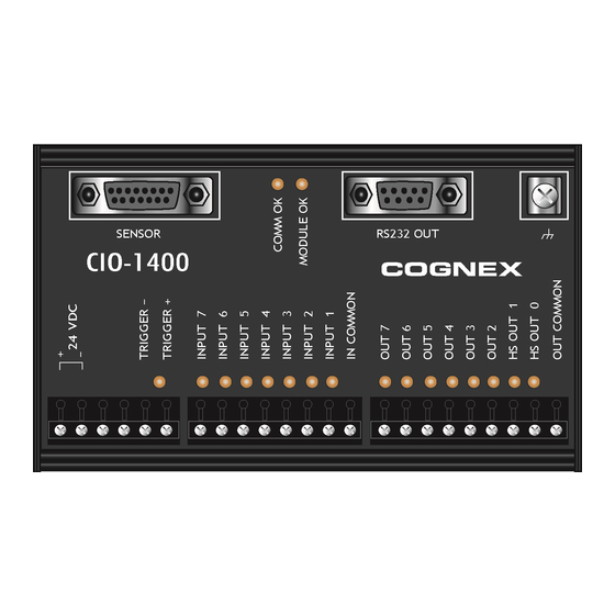
Introduction In-Sight ® In This Section In-Sight Model 1400 I/O Expansion Module Overview ..... 1 In-Sight Support ................ 2 In-Sight Model 1400 I/O Expansion Module Overview ® The In-Sight Model 1400 I/O Expansion Module provides a convenient way to access the power, serial, trigger and high-speed output connections of the In-Sight 3400 and 5000 series sensors. -
Page 16: In-Sight Support
Explorer Help, an online help file accessible from within the In-Sight Explorer software or on the In-Sight CD-ROM. • Installing the In-Sight 3400 Vision Sensor, Cognex P/N 597-0025-xx (English, French, Japanese and German versions available.) • Installing In-Sight 5000 Series Vision Sensors, Cognex P/N 597-0027-xx (English, Spanish, German, French, Japanese, Korean and Chinese (simplified) versions available.) -
Page 17: Installation
Connecting the 1400 I/O Expansion Module This section explains how to connect the 1400 I/O Expansion Module using standard and optional components. For a complete list of options and accessories, contact your Cognex sales representative. Table 2-1: Model 1400 I/O Expansion Module Connectors and Indicators... -
Page 18: Figure 2-1: Connecting I/O Wires
Installation The 1400 I/O Expansion Module outputs labeled HS OUT 0 and HS OUT 1 correspond to the In-Sight 3400 and 5000 series sensor's built-in outputs. These signals are Note: considered high-speed because they pass directly through the expansion module without processing or optical isolation with minimal delay. -
Page 19: Figure 2-2: Connecting The I/O Cable And Serial Cable
In-Sight® 1400 I/O Expansion Module Installation and Reference Manual 7. If you want to connect the In-Sight sensor to a remote serial device, plug the RS-232 serial cable (DB9 connector) into the expansion module. Serial Cable I/O Cable Figure 2-2: Connecting the I/O Cable and Serial Cable 8. -
Page 20: Figure 2-3: Connecting The Expansion Module To An In-Sight Sensor
Installation PWR ENET TROL PAD 24VDC ENET Figure 2-3: Connecting the Expansion Module to an In-Sight Sensor 9. Insert the +24VDC and negative ground wire leads from a 24VDC power supply into the two terminals (labeled +-24 VDC) on the Expansion Module (Figure 2-4). -
Page 21: Configuring The Software
In-Sight® 1400 I/O Expansion Module Installation and Reference Manual -24 VDC +24 VDC Figure 2-4: Connecting Power (+24 VDC and Ground Wires) Configuring the Software Before the 1400 I/O Expansion Module can be used, the In-Sight sensor must be configured to recognize the availability of the additional inputs and outputs and the added RS-232 serial communication capability. -
Page 22: Figure 2-5: Accessing The I/O Output Settings
Installation To configure the sensor using In-Sight Explorer: 1. Connect the 1400 I/O Expansion Module to your In-Sight sensor with an I/O cable as described in the previous section. 2. Start the In-Sight Explorer software and log on to your sensor. 3. -
Page 23: Figure 2-6: Discrete Output Settings
In-Sight® 1400 I/O Expansion Module Installation and Reference Manual Figure 2-6: Discrete Output Settings 4. In the bottom left of the Discrete Output Settings dialog, select CIO-1400 from the Output Module list. The dialog will change to correspond to the available discrete outputs on the 1400 I/O Expansion Module. -
Page 24: Configuring The 1400 I/O Expansion Module Serial Port Settings
Installation 2.2.2 Configuring the 1400 I/O Expansion Module Serial Port Settings Before you configure serial port settings, the expansion module must be recognized by Note: the sensor. (See section 2.2.1.) To configure RS-232 serial port settings: 1. From the Sensor menu, select Serial Port Settings. Figure 2-7: Accessing the Serial Port Settings... -
Page 25: Figure 2-8: Default Serial Port Settings
In-Sight® 1400 I/O Expansion Module Installation and Reference Manual Figure 2-8: Default Serial Port Settings 2. Select the serial communication protocol of your device from the Mode list. 3. Configure the serial port settings (Baud Rate, Parity, Handshake and Details) (if applicable), and click OK to save the new settings to the sensor’s memory. - Page 26 Installation...
-
Page 27: Specifications
Specifications In-Sight ® In This Section General Specifications ............13 Input and Output Specifications ..........14 Connector and Terminal Block Specifications ......18 Dimensions ................21 General Specifications Table 3-1: 1400 I/O Expansion Module General Specifications Specification Description Compatibility In-Sight 3400 and In-Sight 5000 Series Vision Sensors Trigger 1 optically isolated trigger input Inputs... -
Page 28: Input And Output Specifications
Specifications Input and Output Specifications 3.2.1 General Purpose Inputs The 1400 I/O Expansion Module extends the capabilities of supported In-Sight vision sensors by providing seven independent, general-purpose inputs (INPUT 1 - INPUT 7) that can be used to trigger sensor events. General purpose inputs are optically isolated and are typically connected (directly or indirectly) to a sensor (such as a limit switch, pressure switch, or temperature switch). -
Page 29: Trigger Input
In-Sight® 1400 I/O Expansion Module Installation and Reference Manual 3.2.2 Trigger Input The 1400 I/O Expansion Module provides inputs for triggering a connected In-Sight sensor (TRIGGER +, TRIGGER-). When the expansion module is connected to a supported In-Sight sensor, trigger input signals travel directly through the expansion module and are optically isolated in the sensor. -
Page 30: General Purpose Outputs
Specifications 3.2.3 General Purpose Outputs The 1400 I/O Expansion Module extends the capabilities of supported In-Sight vision sensors by providing six independent, general-purpose outputs (OUT 2 - OUT 7) that can be used to trigger remote events. General purpose outputs are optically isolated and are typically connected (directly or indirectly) to a load (such as a relay, indicator light or motor). -
Page 31: High Speed Outputs
In-Sight® 1400 I/O Expansion Module Installation and Reference Manual 3.2.4 High Speed Outputs The 1400 I/O Expansion Module provides two high-speed discrete outputs (HS OUT 0, HS OUT 1) that can be used to trigger remote events. High-speed output signals travel through the I/O module without processing. -
Page 32: Connector And Terminal Block Specifications
Specifications Connector and Terminal Block Specifications 3.3.1 RS-232 Serial Connector The RS-232 serial connector connects a 1400 I/O Expansion Module and a remote serial device. Table 3-6 identifies the signal assignment for each pin on the connector. Table 3-6: RS-232 Serial Connector Pin Assignments Pin # Assignment Pin #... -
Page 33: In-Sight Sensor Connector
In-Sight® 1400 I/O Expansion Module Installation and Reference Manual 3.3.2 In-Sight Sensor Connector The In-Sight sensor connector supplies power to the sensor and allows the sensor to transmit discrete I/O and serial data to and from the 1400 I/O Expansion Module. Table 3-7 shows the signal assignments for each pin on the connector. -
Page 34: Terminal Block Assignments
Specifications 3.3.3 Terminal Block Assignments Table 3-8 shows the signal assignments for each screw terminal on the expansion module's terminal blocks. Table 3-8: Terminal Block Pin Assignment Pin # Assignment Pin # Assignment + 24 VDC INPUT 1 - 24 VDC IN COMMON Not Used OUT 7... -
Page 35: Dimensions
In-Sight® 1400 I/O Expansion Module Installation and Reference Manual Dimensions Dimensions are in millimeters [inches], are for reference only and may change without notice. 130.0 5.12 89.6 3.53 31.7 1.25 46.6 1.84 Figure 3-5: 1400 I/O Expansion Module Dimensions... - Page 36 Specifications...
-
Page 37: Configuring Discrete Outputs
Appendix A In-Sight ® A.1 Configuring Discrete Outputs Configure the parallel digital output lines on an In-Sight sensor through the Discrete Output Settings dialog in In-Sight Explorer. Discrete output signals are written out from the In-Sight Explorer spreadsheet using the WriteDiscrete function. The number of outputs varies depending on the connected In-Sight sensor model. -
Page 38: Line Name
Appendix A - Configuring Discrete Outputs The Discrete Output Settings dialog shows three configurable line parameters: Name, Type and Details. A.1.1 Line Name Assign a new name for an output line by selecting the default name and typing a new name. The name may be up to 15 characters. -
Page 39: Line Details
In-Sight® 1400 I/O Expansion Module Installation and Reference Manual Table A-2: Discrete Output Line Types (Cont.) Type Description Strobe The rising or falling edge of the signal can be used to trigger a strobe. If the Strobe Trigger is set to Rising Edge, the signal is HIGH when the CCD is being exposed, otherwise the signal is LOW. -
Page 40: Line Name
Appendix A - Configuring Discrete Inputs Figure A-2: Discrete Input Default Settings The Discrete Input Settings dialog consists of three configurable parameters: Name, Type and Signal. A.2.1 Line Name Assign a new name for an input line by selecting the default name and typing a new name. The name may be up to 15 characters. -
Page 41: Line Type
In-Sight® 1400 I/O Expansion Module Installation and Reference Manual A.2.2 Line Type Available Line Types are selected from the Type drop-down list. Table A-4: Discrete Input Line Types Type Description User Data General purpose input line; used to drive events in the spreadsheet or to set a value in the spreadsheet via the ReadDiscrete function. - Page 42 Appendix A - Configuring Discrete Inputs...
-
Page 43: Configuring An In-Sight 3400 To Recognize The I/O Module
Appendix B In-Sight ® B.1 Configuring an In-Sight 3400 to Recognize the I/O Module Before the 1400 I/O Expansion Module can be used, the In-Sight 3400 sensor must be configured to recognize the availability of the additional inputs and outputs and the added RS-232 serial communication capability. -
Page 44: Figure B-2: Settings Menu
Appendix B - Configuring an In-Sight 3400 to Recognize the I/O Module Figure B-2: Settings Menu 4. From the Settings menu, select Discrete Output. Figure B-3: Discrete Output Dialog, Default Configuration... -
Page 45: Figure B-4: Discrete Output Dialog, Expansion Module Configuration
In-Sight® 1400 I/O Expansion Module Installation and Reference Manual 5. Open the drop-down list to the left of the OK button and select CIO - 1400. The Discrete Output dialog will automatically reconfigure to correspond to the 1400 I/O Expansion Module, as shown in Figure B-4. -
Page 46: Configuring The Expansion Module Serial Port Settings
Appendix B - Configuring the Expansion Module Serial Port Settings B.2 Configuring the Expansion Module Serial Port Settings Before you configure serial port settings, the expansion module must be recognized by Note: the sensor. (See section B.1.) To configure RS-232 serial port settings: 1. -
Page 47: Wiring Inputs And Outputs
Appendix C In-Sight ® C.1 Wiring Inputs and Outputs The following figures show basic wiring for some of the more common configurations. • A connection to both the ground pin labeled - 24VDC, and the power pin labeled + 24 VDC are required to supply the In-Sight sensor with power. -
Page 48: Trigger From Plc Or Photo Eye - I/O Module Sources Current
Appendix C - Wiring Inputs and Outputs C.1.1 Trigger From PLC or Photo Eye - I/O Module Sources Current The In-Sight sensor trigger input is energized by a 24VDC Common signal from a PLC or a photo eye. Figure C-1: Trigger From PLC or Photo Eye - I/O Module Sources Current... -
Page 49: Trigger From Plc Or Photo Eye - I/O Module Sinks Current
In-Sight® 1400 I/O Expansion Module Installation and Reference Manual C.1.2 Trigger From PLC or Photo Eye - I/O Module Sinks Current The In-Sight sensor trigger input is energized by a +24VDC signal from a PLC or a photo eye. Figure C-2: Trigger From PLC or Photo Eye - I/O Module Sinks Current... -
Page 50: Input From Plc - I/O Module Sources Current
Appendix C - Wiring Inputs and Outputs C.1.3 Input From PLC - I/O Module Sources Current The In-Sight sensor input is energized by a +24VDC signal from a PLC. Figure C-3: Input From PLC - I/O Module Sources Current... -
Page 51: Input From Plc - I/O Module Sinks Current
In-Sight® 1400 I/O Expansion Module Installation and Reference Manual C.1.4 Input From PLC - I/O Module Sinks Current The In-Sight sensor input is energized by a 24VDC Common signal from a PLC. Figure C-4: Input From PLC - I/O Module Sinks Current... -
Page 52: Output To Plc - I/O Module Sources Current
Appendix C - Wiring Inputs and Outputs C.1.5 Output to PLC - I/O Module Sources Current The PLC input is energized by a +24VDC signal from an In-Sight sensor. Figure C-5: Output to PLC - I/O Module Sources Current... -
Page 53: Output To Plc - I/O Module Sinks Current
In-Sight® 1400 I/O Expansion Module Installation and Reference Manual C.1.6 Output To PLC - I/O Module Sinks Current The PLC input is energized by a 24VDC Common signal from an In-Sight sensor. Figure C-6: Output to PLC - I/O Module Sinks Current... -
Page 54: Output To Pilot Light Or Relay - I/O Module Sources Current
Appendix C - Wiring Inputs and Outputs C.1.7 Output To Pilot Light or Relay - I/O Module Sources Current The pilot light or relay is energized by a + 24VDC signal from an In-Sight sensor. Figure C-7: Output to Pilot Light or Relay - I/O Module Sources Current... -
Page 55: Output To Pilot Light Or Relay - I/O Module Sinks Current
In-Sight® 1400 I/O Expansion Module Installation and Reference Manual C.1.8 Output To Pilot Light or Relay - I/O Module Sinks Current The pilot light or relay is energized by a 24VDC Common signal from an In-Sight sensor. Figure C-8: Output to Pilot Light or Relay - I/O Module Sinks Current... -
Page 56: High Speed Output To Strobe Controller - I/O Module Sinks Current
Appendix C - Wiring Inputs and Outputs C.1.9 High Speed Output To Strobe Controller - I/O Module Sinks Current The I/O module can only sink current from a device connected to a High Speed Output; it Note: cannot source current. Figure C-9: High Speed Output To Strobe Controller - (Sink Only) - Page 58 ® In-Sight 1400 I/O Expansion Module Installation and Reference Manual P/N 597-0104-01 www.cognex.com...
Need help?
Do you have a question about the In-Sight 1400 and is the answer not in the manual?
Questions and answers