
Related Manuals for Fife MAXCESS SE-26B


Summary of Contents for Fife MAXCESS SE-26B
- Page 1 FIFE GUIDING SOLUTIONS FIFE SE-26B Operating Instructions Line Guide Sensor MI 1085 1...
-
Page 2: Table Of Contents
CONTENTS INSTRUCTION About these operating instructions ........1-1 Proper use . - Page 3 Setting up a (broken) material or print edge as a reference ....8-5 FIFE-500 Preparing the controller for use ......... . 9-1 Select sensor type .
-
Page 4: Instruction
1 - 1 INSTRUCTION 1 INSTRUCTION About these operating instructions These operating instructions describe the installation, commissioning, operation and maintenance of the SE-26B line sensor and provide important instructions for proper use. These operating instructions are intended for both the system construction master as well as the operator who uses the SE-26B sensor in production. -
Page 5: Improper Use
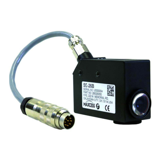
4 Thread for sensor bracket 2 Cover 5 Connection cable to a 3 Nameplate Fife controller Figure 1.1: Line guiding sensor SE-26B The light emitter in the SE-26B sensor generates a light spot on the surface of the material being scanned. Differences in contrast in this area will be sensed by the receiver. -
Page 6: Safety Instructions
2 - 1 SAFETY INSTRUCTIONS 2 SAFETY INSTRUCTIONS Important information Problem-free and reliable operation of the SE-26B requires that the sensor – properly shipped and stored, – properly mounted and placed in operation, – properly used and carefully maintained. Proper operation and careful maintenance will ensure a long service life for the sensor. -
Page 7: Symbols
SAFETY INSTRUCTIONS 2 - 2 Symbols Warning/caution - dangerous area Reference to general hazards that may result in bodily injuries or damage to the device Warning/caution - danger due to crushing Refers to danger of injury caused by crushing Warning/caution - danger due to cutting Refers to danger of injury caused by cutting Additional symbols –... -
Page 8: Maintenance
∙ The parameters specified in Section must be observed. ∙ Only replacement parts that have been approved by Fife-Tidland may be used. ∙ No changes must be made to the sensor. ∙ Electrical lines must not be subjected to any mechanical loads. -
Page 9: Installation
INSTALLATION 3 - 1 3 INSTALLATION Transport and storage – The sensor and/or the unit on which the sensor is mounted must be secured against slipping during transport. – The sensor must be stored in a cool, dry place. – The sensor must not be stored in the vicinity of powerful magnetic fields. -
Page 10: Dimensions
3 - 2 INSTALLATION Dimensions 72.7 53.3 40.3 25.3 25.3 M5-6 tief/ M5-6 tief/ (4.5) M5-6 tief/ 18.7 A Cable length plus connector about 300 mm Figure 3.1: SE-26B Dimensions Mounting location – Protection Class: IP65 – Operating temperature: 0°C ... 50°C –... -
Page 11: Mechanical Fastening
INSTALLATION 3 - 3 Mechanical fastening Holes with M5 threads are available on the housing for Figure 3.1 mounting the sensor ( ). A large variety of assembly options are possible in connection with the various sensor mountings. CAUTION Using long bolts introduces the risk of a short-circuit and destroying the electronics that are located inside the housing. - Page 12 3 - 4 INSTALLATION Sensor bracket type MAMB B Fine positioning C Fine adjustment for focus Figure 3.2: SE-26B with sensor bracket MAMB Type MAMB-25 smooth MAMB-30 smooth Figure 3.3: MAMB MI 1085 1 SE-26B www.maxcess.eu...
- Page 13 INSTALLATION 3 - 5 Sensor bracket type MAMB SE-26B, pivoting B Fine positioning D Pivot point for angle setting C Fine adjustment for focus Figure 3.4: SE-26B with sensor bracket MAMB, pivoting Type MAMB-25 SE-26B smooth 89,5 MAMB-30 SE-26B smooth 93,5 Figure 3.5: MAMB SE-26B www.maxcess.eu...
-
Page 14: Fine Adjustment
3 - 6 INSTALLATION Fine adjustment Fine positioning This setting allows for precise positioning of the light spot on the line/material edge being scanned. Fine adjustment for focus The fine adjustment of the distance between sensor and material web must be made so that the light spot appears well focused on the material web. -
Page 15: Electrical Connection
INSTALLATION 3 - 7 Assembly with glossy materials Assembly with smooth materials Figure 3.7: SE-26B and different material types Electrical connection CAUTION The sensor could be damaged. Electrical connections should always be made or disconnected on the sensor while there is no electrical power in the system. ... -
Page 16: Commissioning
- D-MAXE with Operator Interface OI-TS ( Page 7-1 - D-MAXE with Operator Interface OI-N ( Page 8-1 - DP-20/DP-30 ( Page 9-1 - Fife-500 ( - CDP-01 Sensor Calibration with Line Sensor SE-26 be found in the "CDP-01 Operating Manual." Note: When a complete system is delivered, the web guide controller has already been mostly calibrated in the factory. -
Page 17: Operation
OPERATION 5 - 1 5 OPERATION WARNING: Danger of injury by crushing Do not place your hands on or near moving parts (rollers, material web, etc.) during operation. WARNING: Danger of injury due to cutting on the edge of the material web ... -
Page 18: Edge
- D-MAXE with Operator Interface OI-TS ( (Page 7-3 - D-MAXE with Operator InterfaceOI-N Page 8-3 - DP-20/DP-30 ( Page 9-3 - Fife-500 ( - CDP-01 Sensor Calibration with Line Sensor SE-26 be found in the "CDP-01 Operating Manual." MI 1085 1 SE-26B www.maxcess.eu... -
Page 19: D-Max(E) With Operator Interface Oi-Ts
D-MAX(E) WITH OPERATOR INTERFACE OI-TS 6 - 1 6 D-MAX(E) WITH OPERATOR INTERFACE OI-TS Preparing the controller for use Note: Detailed information about sensor calibration is available in the "D-MAX Operating Instructions". "Supplementary Operating Instructions“ may also be available. Precondition: The SE-24B sensor is connected to the D-MAX(E) controller as specified in the system diagram to X5 or X9. -
Page 20: Setting Up The Asc Function With Broken Line/Edges
6 - 2 D-MAX(E) WITH OPERATOR INTERFACE OI-TS Selecting The properties of a reference are described in section suitable references, page 5-1 ∙ Select job: Press the 4 key until the suitable controller type for - Line center (menu ID J or K) - Material edge or print edge (menu ID L or M) is selected Setting up the... -
Page 21: Setting Up References
D-MAX(E) WITH OPERATOR INTERFACE OI-TS 6 - 3 Setting up references Setting up a (broken) line as a reference Calibrating the analog signal inputs of the D-MAX(E) ∙ Select menu 1y.3.y11.7.1 Calibrate sensor (Button 6 Button 0: 1. Determine the first reference value To do this position the line sensor so that the line is positioned to the left of the light spot. - Page 22 6 - 4 D-MAX(E) WITH OPERATOR INTERFACE OI-TS Setting the polarity The guiding direction (polarity) must be checked depending on the mechanical installation direction of the system and adjusted if necessary. ∙ Select menu 1y.3.y8 (Button 6 Button 8: Polarity) Polarity ∙...
-
Page 23: Setting Up A (Broken) Material Or Print Edge As A Reference
D-MAX(E) WITH OPERATOR INTERFACE OI-TS 6 - 5 Setting up a (broken) material or print edge as a reference Calibrating the analog signal inputs of the D-MAX(E) ∙ Select menu 1y.3.y11.5.1 Calibrate sensor (Button 6 Button 0: 1. Determine the first reference value To do this position the line sensor so that the light spot is positioned completely outside the reference. - Page 24 6 - 6 D-MAX(E) WITH OPERATOR INTERFACE OI-TS Setting the polarity The guiding direction (polarity) must be checked depending on the mechanical installation direction of the system and adjusted if necessary. ∙ Select menu 1y.3.y8 (Button 6 Button 8: Polarity) Polarity ∙...
-
Page 25: D-Max(E) With Operator Interface Oi-N
D-MAX(E) WITH OPERATOR INTERFACE OI-N 7 - 1 7 D-MAX(E) WITH OPERATOR INTERFACE OI-N Preparing the controller for use Note: Detailed information about sensor calibration is available in the "D-MAX Operating Instructions". "Supplementary Operating Instructions“ may also be available. Precondition: The SE-24B sensor is connected to the D-MAX(E) controller as specified in the system diagram to X5 or X9. -
Page 26: Setting Up The Asc Function With Broken Line/Edges
7 - 2 D-MAX(E) WITH OPERATOR INTERFACE OI-N ∙ Select job: Press the 4 key until the suitable controller type for - Line center (menu ID J or K) - Material edge or print edge (menu ID L or M) is selected Setting up the function... -
Page 27: Setting Up References
D-MAX(E) WITH OPERATOR INTERFACE OI-N 7 - 3 Setting up references Setting up a (broken) line as a reference Calibrating the analog signal inputs of the D-MAX(E) ∙ Select menu1y>>6 zum Abgleichen (F6 key Calibration SE-26 ...) ∙ Determine the first reference value To do this position the line sensor so that the line is positioned to the left of the light spot. - Page 28 7 - 4 D-MAX(E) WITH OPERATOR INTERFACE OI-N Setting the polarity The guiding direction (polarity) must be checked depending on the mechanical installation direction of the system and adjusted if necessary. ∙ Select menu 1y>>.3.y8 (F6 key Polarity) Polarity ∙...
-
Page 29: Setting Up A (Broken) Material Or Print Edge As A Reference
D-MAX(E) WITH OPERATOR INTERFACE OI-N 7 - 5 Setting up a (broken) material or print edge as a reference Calibrating the analog signal inputs of the D-MAX(E) ∙ Select menu 1y>>5 for calibration (F6 key Calibration SE-26 ...) ∙ Determine the first reference value To do this position the line sensor so that the light spot is positioned completely outside the reference. - Page 30 7 - 6 D-MAX(E) WITH OPERATOR INTERFACE OI-N Setting the polarity The guiding direction (polarity) must be checked depending on the mechanical installation direction of the system and adjusted if necessary. ∙ Select menu 1y>>.3.y8 (F6 key Polarity) Polarity ∙...
- Page 31 DP-20/DP-30 8 - 1 8 DP-20/DP-30 Preparing the controller for use Note: Detailed information about sensor calibration is available in the "DP-20 Operating Instructions" or the "DP-30 Operating Instructions". Note: The DP-20 must be equipped with firmware version 1.05 or higher.
- Page 32 8 - 2 DP-20/DP-30 ∙ Continue pressing the Sensor key until - Sensor line centre - ý (menu 3D) or SENSOR - Material edge or print edge § (menu 3E) is selected Setting up the function with broken line/edges Selecting the ASC Source ∙...
- Page 33 DP-20/DP-30 8 - 3 Setting up references Setting up a (broken) line as a reference Calibrating the analog signal inputs of the DP-20/DP-30 Select sensor ∙ Select menu 3D.1.4.1 × ÿ 3A.1.4.1 3D.1.4.1 (Manual Basic Calibration Select Sensor) EINRICHTEN (MAN) SETUP (MAN) SENSOR AUSWAHL...
- Page 34 8 - 4 DP-20/DP-30 The DP-20/DP-30 web guide controller will return to the ÿ 3D.1.4.4 operator area if the calibration is successful. SUCCESSFUL -ãããããããããá+ 95% If there is not enough contrast for control, “FAILED” appears in ÿ 3D.1.4.6 the display. FAILED áßßßßßßßßß...
- Page 35 DP-20/DP-30 8 - 5 Set up for broken lines only ∙ Calibrate a material edge or print edge. © 3E.1.4 ü 3D.1.4 Calibrating the analog signal inputs of the DP-20/ SETUP (MAN) SETUP (MAN) see CALIBRATION CALIBRATION DP-30, page 8-5 Position the sensor and line as follows for this calibration: 1.
- Page 36 8 - 6 DP-20/DP-30 ∙ Press the ENTER key Wait a few seconds. The reference value will be determined. ∙ Determine the second reference value © 3E.1.4.3 COVER SENSOR -ãããããããããá+ 95% To do this position the line sensor so that the light spot is positioned completely inside the reference.
- Page 37 DP-20/DP-30 8 - 7 Setting the gain The gain must be set optimally. ∙ Select menu 3E.1.1 © 3E.1.1 (Manual Basic Gain) SETUP (MAN) GAIN ãßßßßßßßßß Gain ∙ Set the Set up for broken material edges or print edges only ASC limits Set the ×...
- Page 38 Note: Detailed information about sensor calibration is available in the „FIFE-500 Operating Instructions“. Precondition: The SE-46C sensor must be connected to the FIFE-500 web guide controller according to the system diagram in the system documentation. Placeholder x: These places in the menu IDs depend on the selected reference type.
- Page 39 FIFE-500 9 - 2 ∙ Press the SENSOR key until the suitable controller type for - Line center (menu ID E) - Material edge or print edge (menu ID D) is selected. www.maxcess.eu SE-26B MI 1085 1...
- Page 40 FIFE-500 Setting up references Setting up a (broken) line as a reference Calibrating the analog signal inputs of the FIFE-500 Sensor Setup ∙ Select menu 1E.1.7 (Setup button Sensor Setup button) ∙ Press the "Start Calibration" button ∙ first reference value To do this position the line sensor so that the line is positioned on the left border within the light spot.
- Page 41 ∙ Press the ACCEPT button to exit menu Set up for broken lines only ∙ Calibrate a material edge or print edge. Calibrating the analog signal inputs of the FIFE-500, See page 9-5 Position the sensor and line as follows for this calibration: 1.
- Page 42 Setting up a (broken) material or print edge as a reference Calibrating the analog signal inputs of the FIFE-500 Sensor Setup ∙ Select menu 1D.1.7 (Press Setup button Press Sensor Setup button) ∙ Press the "Start Calibration" button ∙...
- Page 43 Note: If an error occurs during the calibration, the error will appear in the menu and the calibration must be repeated. Adjusting the FIFE-500 web guide controller Note: The settings must be made for sensor mode D - Material edge...
- Page 44 9 - 7 FIFE-500 Set up for broken material edges or print edges only ∙ Select menu 1D.1.5.1.3 (Setup button ASC button ASC Settings button) ∙ Select the ASC S1 tab ∙ Activate ASC State (LED green) ∙ Select S1 source ∙...
-
Page 45: Maintenance
MAINTENANCE 10 - 1 10 MAINTENANCE WARNING: Danger of injury by crushing. Maintenance work must only be performed on the sensor when the power is turned off and the machine is stopped and protected against being turned on again. Maintenance No regular maintenance is required on the sensor. -
Page 46: Troubleshooting
Solution No Light Spot Cable connection loose. Check the cable connections on the sensor and on the web guide controller No power to Fife guiding Check the power supply on the controller. web guide controller MI 1085 1 SE-26B www.maxcess.eu... -
Page 47: Technical Data
TECHNICAL DATA 12 - 1 12 TECHNICAL DATA General information Supply voltage +/-12V supply from Fife controller Supply current 50mA, +12V 40mA, -12V Sensor Output Line guiding: -20mA bis +20mA Edge guiding: -20mA bis +10mA Ambient conditions Operating: 0°C - 50°C Storage: 0°C - 80°C... -
Page 48: Standards
12 - 2 TECHNICAL DATA Standards The sensor was constructed in accordance with the standards and regulations of the European Union. A Declaration of Conformity is available. MI 1085 1 SE-26B www.maxcess.eu... -
Page 49: Service
This will allow us to help you more quickly in the event that service is required. Adresses To request service, or if you need replacement parts, please contact one of the following addresses. Fife-Tidland GmbH Max-Planck-Straße 8 Siemensstraße 13-15 65779 Kelkheim 48683 Ahaus... - Page 50 13 - 2 SERVICE EUROPE, MIDDLE EAST NORTH, CENTRAL CHINA JAPAN INDIA AND AFRICA AND SOUTH AMERICA Tel +49.6195.7002.0 Tel +1.405.755.1600 Tel +86.756.881.9398 Tel +81.43.421.1622 Tel +91.22.27602633 sales@maxcess.eu sales@maxcessintl.com info@maxcessintl.com.cn japan@maxcessintl.com india@maxcessintl.com www.maxcess.eu www.maxcessintl.com www.maxcessintl.com.cn www.maxcess.jp www.maxcess.in © 2018 Maxcess...
Need help?
Do you have a question about the MAXCESS SE-26B and is the answer not in the manual?
Questions and answers