
Subscribe to Our Youtube Channel
Related Manuals for Fife Maxcess DSE-45 Series


Summary of Contents for Fife Maxcess DSE-45 Series
- Page 1 FIFE GUIDING SOLUTIONS DSE-45 Wideband Ultrasonic Sensor User Manual MI 2-315 1 A...
-
Page 2: Table Of Contents
CONTENTS INTRODUCTION About these operating instructions ................1.1 Target groups ....................... 1.1 Read operating instructions .................. 1.1 Proper use ........................1.2 Improper use ....................... 1.2 Definition of terms ....................... 1.4 SAFETY Important safety information ..................2.1 Signal words ........................ 2.1 Symbols used ....................... - Page 3 CONTENTS Analog output configuration ................. 6.5 Analog output parameter descriptions ............6.6 Calibration ......................6.7 OPERATOR INTERFACE DSE-45 home screen....................7.1 Key (button) definitions ..................7.2 Menu navigation ....................7.4 JOB SETTINGS Setting up a job ......................8.1 Set sensor mode ......................8.2 Single proportional band ..................
- Page 4 CONTENTS TABLE OF FIGURES Figure 1. Product dimensions ....................3.2 Figure 2. Sensor offset to web pass line ................3.3 Figure 3. DSE-45 sensor connections ................. 3.4 Figure 4. Single proportional band ..................4.3 Figure 5. Multiple proportional band ................... 4.4 Figure 6.
-
Page 5: Introduction
Additionally, where applicable, instructions are included for communications with Fife Controllers/Processors, such as the Fife D-MAX Web Guide Controller. These instructions are to be used in addition to those instructions provided with the controller/processor. -
Page 6: Proper Use
INTRODUCTION Proper use The DSE-45 is used for non-contact measurement of the lateral offset of a material web being guided in a customer system. The sensor is suitable for - Web edge guiding, - Web center guiding, and - Web width or edge position measurement. The sensor can be used to control or measure both opaque and transparent materials. - Page 7 Both analog and digital output signals are provided. The DSE-45 Ultrasonic Sensor can be used in conjunction with the Fife Controllers/Processors as a guiding system. If the sensor is connected to a D-MAX Operator Interface via an Ethernet connection, multiple menus are available for configuring the sensor.
-
Page 8: Definition Of Terms
DSE-45. MAC Address is also referred to as MAC-ID. MAXNET – This is the Fife proprietary Ethernet protocol that is used for communications between DSE-45 and D-MAX devices. This is a deterministic protocol. Therefore, the MAXNET network must be isolated from other Ethernet networks that do not follow this protocol. -
Page 9: Safety
SAFETY Important safety information To ensure safe and problem-free operation of the DSE-45 it must be - properly shipped and stored, - properly mounted and placed in operation, - properly used and carefully maintained. Proper operation and careful maintenance will ensure a long service life for the sensor. -
Page 10: Symbols Used
SAFETY Symbols used Reference to general hazards that may result in bodily injuries Refers to danger of injury caused by crushing Refers to danger of injury caused by cutting Refers to general hazards that will result in damage to the device or system Qualified electrician The electrical components may only be connected and... -
Page 11: Personnel Requirements
- Personnel or trainees trained and supervised by the system operator Repair Specialized staff Service technician of Fife-Tidland GmbH Qualified electrician A qualified electrician is a person whose specialist training, knowledge and experience, as well as knowledge of the relevant standards, enable him to assess and perform the work assigned to him and to recognize and avoid possible hazards. -
Page 12: Preventing Hazards
Only accessories and replacement parts that have been approved by Fife Tidland may be used. The sensor may not be used as a support, handle or step. There is a danger that the sensor will become damaged (breaking off/snapping), resulting in personal injury. -
Page 13: Installation
INSTALLATION Transport and storage The sensor and/or the unit on which the sensor is mounted must be secured against slipping during transport The sensor must be stored in a cool, clean, and dry place; Ambient Conditions, page 11.1 The sensor must not be stored in the vicinity of powerful magnetic fields. -
Page 14: Product Dimensions
INSTALLATION Product dimensions 1 - Sensor gap (typical for all sensors) 2 - M5 x 20 mm SHCS with lock washer 3 - The minimum bend radius of the optional Ethernet cable is 90 mm [3.54 in]. The minimum bend for output and auxiliary cables is less. Figure 1. -
Page 15: Mounting The Sensor
INSTALLATION Mounting the sensor Remove the plastic dust covers from the connectors that will be in use for your application. For complete details, refer to the installation drawings and instruction sheets included with your shipment. Center line of sensor should be offset 15 degrees or more of perpendicular to the web pass line. -
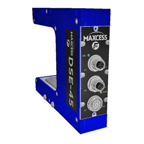
Page 16: Dse-45 Sensor Connections
X2 Connector. Follow the voltage guidelines in Figure 3. When used as part of a Fife system, the Controller/ Processor generally supplies power to the X3 connector. If alternate power is to be supplied, refer to the system drawings for information on power supply requirements. -
Page 17: Network Connection
Web Access Network; page 6.1. - MAXNET is a Fife proprietary protocol used to communicate between the DSE-45 and other network devices, such as the Fife D-MAX Controller and D-MAX Operator Interface. - The MAXNET address of each Ethernet device in a network must be unique (Address 1-31). -
Page 18: Operation Overview
Ethernet digital interface for advanced functions. The DSE-45 Ultrasonic Sensor can be used in conjunction with the Fife Controllers/Processors as a guiding system. If the sensor is connected to a D-MAX Operator Interface via an Ethernet connection, multiple menus are available for configuring the sensor. -
Page 19: Analog Outputs
OPERATION OVERVIEW Analog outputs There are four configurable analog outputs, controlled by three configurable signal sources. The analog outputs can be independently configured to produce any combination of the following signal ranges. The analog output mapping can be configured for each of the sensor jobs. An Ethernet connection to the sensor is required for configuration changes. -
Page 20: Digital Outputs
OPERATION OVERVIEW Digital outputs The digital outputs are transmitted via a proprietary Fife MAXNET Serial Protocol over Ethernet, which requires an optional Ethernet cable connected to a network device. For more information about the available signals; DSE-45 Web Page, page 6.6. -
Page 21: Operation Modes
OPERATION OVERVIEW Operation modes The DSE-45 can be operated in either of two modes. Single proportional band mode To monitor the position or width of more than one web, use Multiple page 8.3 Proportional Band mode; The default Single Proportional Band operation mode of the DSE-45 used for guiding and web width monitoring of a single web. -
Page 22: Multiple Proportional Band Mode
Figure 5 illustrates the general nature of this mode of operation. Configuration of this mode requires an Ethernet connection to a network device, such as a PC or a Fife D-MAX Operator Interface. This mode enables additional menu-controlled features, including Proportional Band Size, Learn Edges, and Virtual page 8.4. - Page 23 OPERATION OVERVIEW Features available in Multiple Proportional Band mode Learn Edges provides a method to automatically build virtual sensor(s) based on the position of webs that are placed in the sensor field of view. The number of virtual sensors built depends on the number of web edges detected.
-
Page 24: Modbus/Tcp Interface
MODBUS/TCP INTERFACE Modbus/TCP interface The DSE-45 provides Modbus/TCP slave capability. An optional Ethernet cable is required for communication between the sensor and a network device. The default settings - permit the collection of lateral position information for up to eight webs (sixteen edges), and - support remote control commands for virtual sensor operations such as learning edge positions and shifting virtual sensors individually or in groups. -
Page 25: Default Data
MODBUS/TCP INTERFACE Default data The default data available from DSE-45 Modbus slave is as follows. DSE-45 to Customer (57 words) Register Parameter Description Reserved Reserved. RemReqCmd Remote control command. (See remote control) RemReqStatus Remote control status. (See remote control) RemReqParam1 Remote control parameter. -
Page 26: Figure 7. Modbus Default Data
MODBUS/TCP INTERFACE Customer to DSE-45 (4 words) Register Parameter Description Command Remote control command. Parameter1 New position (for absolute or relative shifting) Parameter2 Mask indicating which virtual sensors are included (if applicable) Parameter3 Shift speed (for shifting operations) Figure 7. Modbus default data www.maxcessintl.com DSE-45 MI 2-315 1 A... -
Page 27: Remote Control
MODBUS/TCP INTERFACE Remote control Issuing commands via Modbus/TCP can control various aspects of the sensor operation. Commands are issued by writing a recognized command and its associated parameters in the respective data words designated for remote commands. The DSE-45 will act once on the initial receipt of a new command and issue feedback in the designated outgoing data words. - Page 28 MODBUS/TCP INTERFACE Even though the DSE-45 acts only once on the initial receipt of a new command, after the command has completed it is recommended that the command and all parameters be cleared. The command word contains fields that are needed by some commands and ignored by others.
- Page 29 MODBUS/TCP INTERFACE Cancel any pending operation. This command can also be Cancel 0x1000 used to "ping" the sensor to verify its presence. Command Syntax: UNIT Parameter1 Not used. Parameter2 Not used. Parameter3 Not used. Response: RemReqCmd Duplicates the supplied command. RemReqStatus 1 = Command completed.
- Page 30 MODBUS/TCP INTERFACE Move VS Absolute 0x4xxx Move virtual sensor to an absolute position. Command Syntax: UNIT Parameter1 Required Positive value indicating the desired virtual sensor position. It is interpreted according to the UNIT field described below. Parameter2 Optional Parameter used when LNK = 1 to move one or more virtual sensors when the target virtual sensor moves.
- Page 31 MODBUS/TCP INTERFACE Parameter2 mask: (set the target virtual sensor bit and any additional bits to link multiple virtual sensors) VS16 VS15 VS14 VS13 VS12 Response: RemReqCmd Duplicates the supplied command. RemReqStatus 1 = Command completed. 2 = Command is in progress (shifting). Negative value indicates an error (see RemReqStatus values described previously).
- Page 32 MODBUS/TCP INTERFACE Move VS Relative 0x5xxx Move virtual sensor relative to its current position. Command Syntax: UNIT Parameter1 Required Signed value indicating the desired distance and direction to move the specified virtual sensor. It is interpreted according to the UNIT field described below.
- Page 33 5.10 MODBUS/TCP INTERFACE Parameter2 mask: (set the target virtual sensor bit and any additional bits to link multiple virtual sensors) VS10 Response: RemReqCmd Duplicates the supplied command. RemReqStatus 1 = Command completed. 2 = Command is in progress (shifting). Negative value indicates an error (see RemReqStatus values described previously).
- Page 34 5.11 MODBUS/TCP INTERFACE Set PB 0x9xx0 Set the virtual sensor proportional band size. Size Command Syntax: UNIT Parameter1 Required Specifies the new virtual sensor proportional band size. All virtual sensors in the selected job will use the specified size. Parameter2 Not used Parameter3 Not used...
-
Page 35: Web Page Access
DSE-45 WEB PAGE Web page access The DSE-45 contains an integrated HTTP server that provides web page access to the sensor configuration parameters. This requires an optional Ethernet cable connected to a network device, such as a PC, that contains a web browser. To communicate with the DSE-45, the PC and the web browser must be configured to match the DSE-45 network settings. -
Page 36: Dse-45 Web Page Tab Descriptions
DSE-45 WEB PAGE DSE-45 web page tab descriptions Home is displayed when communication is first established with the DSE-45. It contains information about the job that is currently running and provides an animation that reflects the state of the web(s) in the sensor field of view. -
Page 37: Info
DSE-45 WEB PAGE Info contains information about the sensor, such as Serial Number, Network Settings, Firmware and Software versions, Proportional Band size (including the number of transducer pairs that make up the Proportional Band) and other info related to the configuration of the sensor. - Page 38 The MaxNet ID is important only if the sensor is communicating with another Fife network device incorporating the MaxNet protocol, such as a D-MAX Controller or Operator Interface.
-
Page 39: Analog Output Configuration
DSE-45 WEB PAGE Analog output configuration contains fields that apply to the analog outputs. These fields can be edited: 1. Enter the desired value in the proper field, and then 2. Click the "Apply Changes" button. The changes are effective immediately. There are four configurable analog outputs, controlled by three configurable signal sources. -
Page 40: Analog Output Parameter Descriptions
DSE-45 WEB PAGE Analog output parameter descriptions Signal source The source of the signal that controls the analog outputs via the analog channels. (The source can be configured for each of the three analog channels, and for each Job, independently). Analog Channels 1 and 2, by default, provide edge position (the first on- web edge detected and the first off-web edge detected, respectively). -
Page 41: Calibration
Calibration contains a means to calibrate the sensor to the material being guided. (This calibration is independent from Sensor Calibration in the Fife Controller/Processor). The DSE-45 is factory-calibrated to an acoustically opaque material. Generally, it is not necessary to recalibrate the sensor. If the material to be guided is not acoustically opaque, it may be possible to improve the performance of the sensor by performing this calibration. -
Page 42: Operator Interface
OPERATOR INTERFACE DSE-45 home screen The information and procedures in this section assume the use of an optional Ethernet cable, connecting the DSE-45 to a network device, such as the D-MAX Operator Interface. Figure 9. DSE-45 home screen - Press the ENTER key to enter menu mode or advance to the next menu level. -
Page 43: Key (Button) Definitions
OPERATOR INTERFACE Key (button) definitions A. Screen Select key This key is used to scroll through the devices that exist on the network. Hold the key for at least two seconds to display a list of the devices. B. F1 key This key is not used by the DSE-45. - Page 44 OPERATOR INTERFACE L. Left Arrow key In the menu levels, this key is used to enable/disable entries in the displayed list and to move the cursor when editing values. M. Right Arrow key In the menu levels, this key is used to enable/disable entries in the displayed list and to move the cursor when editing values.
-
Page 45: Menu Navigation
OPERATOR INTERFACE Menu navigation The information and procedures in this section assume the use of an optional Ethernet cable, connecting the DSE-45 to a network device, such as the D-MAX Operator Interface. While in these menus, the selected entry is surrounded by a rectangular box and is shown in the information area of the display. -
Page 46: Job Settings
JOB SETTINGS 1X.3 Setting up a job At the home screen, press to enter the Job Settings menu. The following menu structure illustrates sensor operation modes and features for each mode. Set Sensor Mode; page 8.2. From the DSE-45 Home Screen, press the ENTER key to enter the menus, select "Job Settings", then press ENTER. -
Page 47: Set Sensor Mode
JOB SETTINGS Set sensor mode 1X.3.1.1 Single proportional band In Single Proportional Band, the position of each edge is in relation to the full proportional band of the sensor. Press to select Single Proportional Band [1X.3.1.1.1] www.maxcessintl.com DSE-45 MI 2-315 1 A... -
Page 48: Multiple Proportional Band
JOB SETTINGS 1X.3.1.2 Multiple proportional band In Multiple Proportional Band, the position of each edge is in relation to the proportional band of the virtual sensor in which the edge is located. If Multiple Proportional Band is selected, the following features can be configured: 1X.3.1.2.1 Proportional band size 1X.3.1.2.2 Learn edges linking... -
Page 49: Edge Learning
JOB SETTINGS 1X.3.1.2.1 Proportional band size In Multiple Proportional Band, the size of the virtual sensors can be changed. Changes in this parameter are applied to all virtual sensors and take effect immediately. The minimum size of the virtual sensors is 10.2 mm [0.402 inches]. -
Page 50: 1X.4 Select Job
JOB SETTINGS 1X.4 Select job Job selection changes must be performed with the Controller/Processor in either Manual mode or Servo-Center mode only. To enter the Select Job menus, follow the Select Job menu structure in Figure 5. Use these menus to select the desired job. (If the desired job is not listed, go to the Control Options >... -
Page 51: Calibrate Transducers
JOB SETTINGS Calibrate transducers Calibration is necessary when using materials that are acoustically transparent. To properly detect material edges, each transducer channel will need to register as "covered" below a higher signal level threshold than with acoustically opaque materials. Use the Hardware Settings menu (Figure 12) to calibrate the transducers. -
Page 52: Control Options
JOB SETTINGS Control options To view or modify any of the following, follow the Control Options menu structure in Figure 13 Job enable Use these menus to enable/disable the desired jobs. Remote control Use these menus to enable or disable control from remote devices;... -
Page 53: Configuration
JOB SETTINGS Configuration To view or modify any of the Configuration Settings, follow the menu structure in Figure 14. Names Use these menus to view or modify the Device and Usage names of the selected Controller. Serial Number The Model Number and Serial Number of the DSE-45 (Device) are displayed. -
Page 54: Network
JOB SETTINGS Network TCP/IP Use Network menus to view or edit the Ethernet IP-Address, Subnet Mask, or Gateway. Also, use this menu to enable or disable (ON/OFF) DHCP. If DHCP is set to ON and the DHCP Server is not connected or operating at the time the DSE-45 is powered up, after 30 seconds the DSE-45 adopts the currently stored IP Address so that the system can initialize. - Page 55 8.10 JOB SETTINGS Service menu Service Menu To view any of the Service menus, follow the Structure; page 11. Measuring points Use these menus to view the current values of the DSE-45 output signals, various power points, internal temperatures, and network statuses. www.maxcessintl.com DSE-45 MI 2-315 1 A...
-
Page 56: Figure 16. Service Menu Structure
8.11 JOB SETTINGS Service menu structure From the SE-45 Home Screen, press the ENTER key to enter the menus, select "Service", then press ENTER. Status # 1X.9 Service Measuring 1X.9.1 Points 1X.9.1.1 Signals 1X.9.1.1.1 Edges The position of the currently 1X.9.1.1.1.1 Edge 01:XXX.X detected edges is displayed. -
Page 57: Specific Procedures
SPECIFIC PROCEDURES Jog virtual sensors The Jog function allows the operator to shift the position of selected virtual sensors. If multiple virtual sensors are linked, the linked virtual sensors will follow the shifted virtual sensor. If the sensor mode setting is Multiple Proportional Band, the command will be displayed next to the F5 key on the DSE-45 home screen. -
Page 58: Application Filtering
SPECIFIC PROCEDURES Application filtering Refer to the Application Filtering Examples on the pages following these The DSE-45 can be configured so that a D-MAX Operator Interface (OI) will be denied communication with the DSE-45. This may be desired so that unauthorized personnel do not have access to the internal settings of the DSE-45. - Page 59 SPECIFIC PROCEDURES - The Sub Function Number represents the function of the device in an application. The default setting for the Sub Function is 0 (zero). For an operator interface to communicate with only a specific device in multiple applications, the primary device in each application that is to be controlled by the operator interface must have the Sub Function set to 0 (zero).
- Page 60 SPECIFIC PROCEDURES Configure the DSE-45 Configuration Menu Structure, page 8.8. Reference: 1. From an operator interface, select the desired DSE-45. 2. From the DSE-45 Home Screen, press the ENTER key to enter the sensor menus. 3. Select "Configuration", and then press the ENTER key. 4.
- Page 61 SPECIFIC PROCEDURES Configure the operator interface The next step is to configure the Operator Interface unit(s) that will be communicating with the configured DSE-45 sensor(s) by performing the procedure for your chosen option. Option 1. To "hide" a DSE-45 sensor so that it does not show up in the list of devices on the operator interface, perform the following procedure.
- Page 62 SPECIFIC PROCEDURES Option 2. If the operator interface is to communicate with a primary device or devices in all application groups, perform the following procedure. Press longer than two seconds Control Options 1.a.2 Application Filter 1.a.2.2 1.
- Page 63 SPECIFIC PROCEDURES Option 3. If the operator interface is to communicate with all of the devices in a specific application group (Application ID), perform the following procedure. Press longer than two seconds Control Options 1.a.2 ...
- Page 64 SPECIFIC PROCEDURES Assigning names for "All Applications" filtering If desired, names for the DSE-45 sensors can be assigned. Configuration 1.a.7 Names 1.a.7.1 Usage 1.a.7.1.2 To edit name 1.a.7.1.2.1 ...
- Page 65 SPECIFIC PROCEDURES Assigning names for "Selected Applications" filtering If desired, names for the devices and/or drives can be assigned. Configuration 1.a.7 Names 1.a.7.1 Usage 1.a.7.1.2 To edit name 1.a.7.1.2.1 ...
- Page 66 9.10 SPECIFIC PROCEDURES Filtered / All (F5) key When Application Filtering is properly set up and enabled, this key is available to select the contents of the list of devices on the "All Devices" screen. 1. From the home screen, press and hold the Screen Select (A) key for at least two seconds.
-
Page 67: Maintenance
10.1 MAINTENANCE Maintenance The DSE-45 can be remotely controlled via a network connection. As with any network-controlled device, when remote control of the device is implemented, there is the possibility of movement of the guiding structure when remote commands are issued. Therefore, any time personnel are near the guiding structure, it is recommended that standard safeguards be taken to prevent injury. -
Page 68: Specifications
X2 connector 10.5 to 51 VDC min/max (Customer supplied power) Input voltage range, 12 to 24 VDC nominal at the X3 connector 10.5 to 28 VDC min/max (Power supplied by Fife controller) Power consumption DSE-45-7 .225 Amps DSE-45-11 .235 Amps DSE-45-18 .245 Amps... - Page 69 11.2 SPECIFICATIONS Inputs and outputs Communication port Ethernet based – 100 Mbps – Auto MDIX (Medium- Dependent Interface Crossover) Sensor output (4) (2 connectors) Maximum output +20 mA Individually programmable 0 to 10 mA (default), 400 ohm load, maximum 0 to 20 mA (available), 125 ohm load, maximum 4 to 20 mA (available), 125 ohm load, maximum Cable restrictions Connection to X1, Ethernet...
-
Page 70: Service
12.1 SERVICE Service requests and replacement parts To request service or to get replacement parts, contact one of the following addresses: Fife Corporation 222 West Memorial Rd. Oklahoma City, OK, 73114, USA Phone: 1.405.755.1600 Fax: 1.405.755.8425 Web: www.maxcessintl.com Fife-Tidland GmbH...
Need help?
Do you have a question about the Maxcess DSE-45 Series and is the answer not in the manual?
Questions and answers