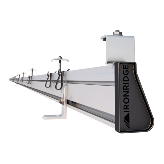
Summary of Contents for IRONRIDGE Standard Rail Roof Mounting
- Page 1 Standard Rail Roof Mounting Installation Manual www.ironridge.com | 800-227-9523 | Rev B, May 2012 | This manual’s part #: 91-0700-004 © Copyright 2012 IronRidge, Inc. All rights reserved.
-
Page 2: Installer Responsibility
2. Customer Support IronRidge makes every effort to ensure your mounting kit is easy to install. If you need assistance at any point with your installation or have suggestions on how we can improve your experience, call IronRidge customer support: (707) 459-9523 3. - Page 3 Installation Standards (NEIS™), UL Standards, and OSHA Regulations. For installations that utilize WEEBs, WEEB Lugs and WEEB Bonding Jumpers, please refer to Wiley/Burndy installation manual for “IronRidge Light and Standard Series Rail” for proper installation procedures. www.ironridge.com | 800-227-9523 © Copyright 2012 IronRidge, Inc. All rights reserved.
-
Page 4: Component List
| Standard Rail Installation Manual 6. Component List The IronRidge Standard Rail System contains the following parts: Note: The component list indicated here is for reference only. The actual component quantities will vary according to the quantity and make of modules that the mount is configured for. Please check the packing list that ships with every mount for a confirmation of the items that are intended to ship with the specific product on your order. - Page 5 Part number changes depending on panel used. Example part numbers shown. End Clamp 51-6000-xxx 1/4-20 x 1” SS hex-cap bolt, SS 23-2520-100 1/4-20 flange nut, SS 25-2501-014 Standard Rail Spares Kit 29-7000-001 www.ironridge.com | 800-227-9523 © Copyright 2012 IronRidge, Inc. All rights reserved.
- Page 6 1/4-20 x 1” SS hex-cap bolt, SS 23-2520-100 1. Mount all of the feet to the roof in the desired locations. Note: Determine the maximum distance between feet according to engineering specifications. www.ironridge.com | 800-227-9523 © Copyright 2012 IronRidge, Inc. All rights reserved.
- Page 7 1/4-20 x 2.50” hex cap bolt, SS, or 23-2520-250, 1/4-20 x 2.75” hex cap bolt, SS 23-2520-275 End Clamp Kit 29-7000-xxx 1/4-20 x 1” SS hex-cap bolt, SS 23-2520-100 www.ironridge.com | 800-227-9523 © Copyright 2012 IronRidge, Inc. All rights reserved.
- Page 8 7. By moving this second rail along its foot- ings, the internal splice should slip into the cavity on the first rail, with the rails butting tightly and evenly together. www.ironridge.com | 800-227-9523 © Copyright 2012 IronRidge, Inc. All rights reserved.
- Page 9 Light and Standard Series Rails” for proper installation proce- dures.) 1. Then slip the end clamp over the bolt, making sure it is firmly hooked over the side of the module. www.ironridge.com | 800-227-9523 © Copyright 2012 IronRidge, Inc. All rights reserved.
- Page 10 (Note- For installations that utilize WEEBs, please refer to Wiley/Burndy in- stallation manual for “IronRidge Light and Standard Series Rails” for proper installation proce- dures.) www.ironridge.com | 800-227-9523 © Copyright 2012 IronRidge, Inc. All rights reserved.
- Page 11 7. Repeat the procedure using center clamps to secure each successive module. 8. Secure the last module at the end of the rails using the other set of end clamps. www.ironridge.com | 800-227-9523 © Copyright 2012 IronRidge, Inc. All rights reserved.
- Page 12 Product is required with any warranty claim. Except as set forth above, IronRidge sells the Products on an “AS IS” basis, which may not be free of errors or defects, and ALL EXPRESS OR IMPLIED REPRESENTATIONS AND WARRANTIES, INCLUDING ANY WARRANTIES...


Need help?
Do you have a question about the Standard Rail Roof Mounting and is the answer not in the manual?
Questions and answers