
Related Manuals for LORD D1


Summary of Contents for LORD D1
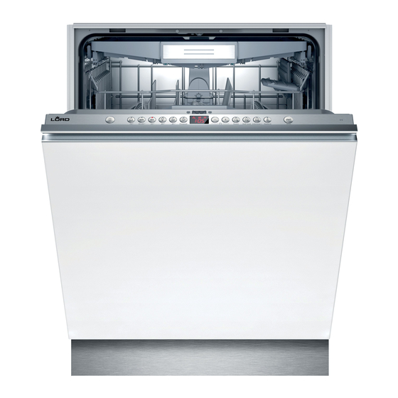
- Page 1 Availability of spare parts and Repair and Maintenance Information HOUSEHOLD Bezpečnost DISHWASHERS...
-
Page 2: Availability Of Spare Parts
Availability of spare parts Bezpečnost The following spare parts can be ordered by professional repair shops at this email address: info@awservice.cz, with the subject of the message „Spare parts order (a)“ motor; circulation and drain pump; heaters and heating elements, including heat pumps (separately or bundled); piping and related equipment including all hoses, valves, filters and aquastops;... - Page 3 Maintenance Information - D1 Model D1, EAN: 4251539600339, Serial number: 1xxxxxxxxx21153960033x Important information 4.8.1 Removing detergent cover 4.8.2 Inserting spring 1.1 Important information 4.8.3 Installing detergent cover 1.1.1 Purpose 4.9 Replacing wastewater pump cover 1.2 Explanation of symbols 4.9.1 Removing wastewater pump cover 1.2.1...
- Page 4 Maintenance Information - D1 4.21 Replacing EmotionLight 4.21.1 Removing EmotionLight 4.21.2 Installing EmotionLight 4.22 Replacing TimeLight 4.22.1 Removing TimeLight 4.22.2 Installing TimeLight 4.23 Replacing Gap illumination 4.23.1 Removing Gap illumination 4.23.2 Installing Gap illumination...
-
Page 5: Explanation Of Symbols
Important information Concerning this document 1.1 Important information 1.2 Explanation of symbols 1.1.1 Purpose 1.2.1 Danger levels These repair hints support consumer to repair appliances by himself according to the The warning levels consist of a symbol and a signal word. The signal word indicates applicable eco-design regulation (as of 03/2021). - Page 6 Important information Hazard symbol Meaning Gen. symbol Meaning Danger from hot surfaces Identification of required tools Identification of required preconditions Identification of a condition (if ..., then ...) Danger from strong magnetic field Identification of a result Start Identification of a key or button Danger from non-ionizing radiation [00123456] Identification of a material number...
-
Page 7: General Safety Instructions
Safety Safety 2.1 General Safety instructions 2.1.1 All domestic appliances Risk of electric shock due to live parts! ¡ Errors by repairs involving electrical components can lead to electrical shock! ¡ Disconnect the appliance from the mains for at least 60 seconds before starting work. -
Page 8: Tools And Aids
Tools and aids Tools and aids Designation Details Images Screwdriver Torx 100 mm, for screws with safety T20 with bore hole [00340764] Insulated Screw- Blade length 125 mm, for driver Torx T15 with screws with safety pin bore hole [15000626] Slotted screwdriver Blade 10 mm x 1.6 mm x 200 mm Needle nose pliers Length: 200 mm, straight... - Page 9 Repair Repair 4.1 Replacing worktop 4.1.2 Installing worktop 1. Lock the rear of the worktop into the guides using the retaining collars (1). Prerequisite: Appliance is disconnected from the power supply. Appliance is freely accessible. 4.1.1 Removing worktop 1. Remove the two screws at the back (1) (optional). 2.
- Page 10 Repair 4.2 Installing basket system 2. Click the cup support clip into place. Prerequisite: The relevant basket has been removed from the appliance. 4.2.1 Installing a tab slide for the 86 cm model Required tools: Tabguide [00614935] Cup support clip [00618565] 1.
- Page 11 Repair 4. Position the items to be washed. ▶ Wedge the steamer insert with the end pieces under the basket system. 4.2.3 Installing steamer insert Required tools: Tabguide [00614935] Cup support clip [00618565]...
- Page 12 Repair 4.3 Replacing varioDrawer 3. Press plastic side inserts outwards and press them upwards out of the frame. 4.3.1 Removing varioDrawer 1. Bend the handle flaps inwards. 2. Remove the handle upwards.
- Page 13 Repair 4. Carefully bend the guide tabs outwards. 6. Press metal frame at the front out of the holders. 5. Pull the folding spines out of the tabs. 7. Push metal frame back out of the guide. 4.3.2 Installing varioDrawer ▶...
- Page 14 Repair 4.4 Replacing spray arms 4.4.1 Removing spray arm 1. Unscrew the upper spray arm (1) and pull down to remove (2). 2. Pull down the lower spray arm to remove. 4.4.2 Installing spray arm 1. Insert the lower spray arm. The spray arm clicks into position.
-
Page 15: Replacing Filters
Repair 4.5 Replacing filters 4.5.1 Removing filter 1. Turn the coarse filter anticlockwise (1) and remove the filter system (2). Check that no foreign objects fall into the sump. 2. Pull down the micro filter to remove. 4.5.2 Installing filters 1. - Page 16 Repair 4.6 Installing baking sheet spray head 1. Remove top basket. 2. Insert the baking sheet spray head in the holder (1) and turn to the right (2). The baking sheet spray head clicks into position.
-
Page 17: Replacing Power Cord
Repair 4.7 Replacing power cord ▶ Insert the plug of the power cord into the mains socket until the plug clicks audibly into place. Prerequisite: Appliance is disconnected from power supply. Appliance is disconnected from water supply. Appliances is freely accessible. 4.7.1 Unplugging power cord Move the plug of the power cord carefully up and down and pull it out of the mains ▶... - Page 18 Repair 4.8 Replacing detergent cover 4.8.2 Inserting spring 1. Insert the long end of the spring into the mounting hole of the dispenser device (1). A small screwdriver can be used as a levering tool. Prerequisite: Appliance is disconnected from power supply. Appliance is disconnected from water supply.
- Page 19 Repair 4.9 Replacing wastewater pump cover Prerequisite: Basket has been removed. Filters has been removed.→ Page 220 4.9.1 Removing wastewater pump cover 1. Scoop out any water. Use a sponge if necessary. 2. Prise off the pump cover using a spoon and grip it by the crosspiece. 3.
- Page 20 Repair 4.10 Replacing side panel 4.10.1 Removing side panel 1. Remove screws from the side panel (1). Prerequisite: Appliance is disconnected from power supply. Appliance is disconnected from water supply. Appliances is freely accessible. Free-standing appliances: Worktop has been removed.→ Page 214 Fig. 1: Fully integrated 2.
- Page 21 Repair 4.10.2 Installing side panel 1. Insert the side panel into the base trough (1). Fig. 2: Fully integrated 2. Press the side panel onto the appliance (2). 3. Secure the side panel with screws (3).
- Page 22 Repair 4.11 Replacing outer door Remove two screws. Prerequisite: Appliance is disconnected from power supply. Appliance is disconnected from water supply. 4.11.1 Removing outer door Just remove the screws which are described in the following steps. 1. Open door. 2. Remove four screws. 4.11.2 Installing outer door Notice Cables which are incorrectly positioned or not secured!
- Page 23 Repair Prerequisite: Open the door and secure it with two screws (4 x 11 mm metal screws). Insulating fleece has been correctly positioned and fixed on the inside of the outer door. Hinges are inserted into the outer door. 1. Close the inner door without snapping it shut. 2.
- Page 24 Repair 4.12 Replacing control panel 5. Remove six screws. If an operating module is defective, the entire control panel must be re- placed. Prerequisite: Appliance is disconnected from power supply. Appliance is disconnected from water supply. Outer door has been removed. Outer door has been removed (fully integrated/integrated).
- Page 25 Repair 4.13 Fix door springs 2. 1. Open door slightly (1). 2. Fix in the groove of the base trough (2). 1. Remove cord guide cover out. 3. Slowly close the door (3). The cord system attaches itself automatically to the door hinge.
- Page 26 Repair 3. 1. Slightly close the door (4). 2. Move the groove to the back and release the door hinge (5). 3. Open the door (6). 4. Repeat the process again on other side of appliance.
- Page 27 Repair 4.14 Replacing toe panel 4. Remove the feet forwards (1). The feet are identical and can be swapped over. Prerequisite: Appliance is disconnected from power supply. Appliance is disconnected from water supply. Outer door has been removed. Outer door has been removed (fully integrated/integrated). 4.14.1 Removing toe panel Incorrect removal.
- Page 28 Repair 4.15 Replacing base socket plate 3. Tilt the base socket plate carefully forwards (1). The base socket plate is located in the lower area at the front. Prerequisite: Appliance is disconnected from power supply. Appliance is disconnected from water supply. Furniture panel (optional) has been removed.
- Page 29 Repair 4.16 Replacing overflow conduit 2. Release catch element at top. The overflow conduit is located in the front lower area of the appliance. Prerequisite: Appliance is disconnected from power supply. Appliance is disconnected from water supply. Furniture panel has been removed (optional). Outer door has been removed.
- Page 30 Repair 4. Lift overflow conduit off. 1. 1. Place overflow conduit (1). 2. Move overflow conduit into seal (2). 3. Press overflow conduit in guide of seal (3). 4. Insert overflow conduit concisely (4). 5. Clip in overflow conduit (5). 4.16.2 Installing overflow conduit Water damage due to incorrect installation of the overflow conduit! Correctly insert the overflow conduit at the bottom into the guide of the...
- Page 31 Repair 2. Check installation left and right. 3. Check firm seat. 4. Clip in metal clip on left and right side.
- Page 32 Repair 4.17 Replacing inner door 6. Secure door hinge with screws. 7. Place inner door on door hinge. Prerequisite: Appliance is disconnected from power supply. 8. Secure inner door with screws. Appliance is disconnected from water supply. 4.17.1 Removing inner door 1.
- Page 33 Repair 4.18 Replacing door hinge 2. Release ground connection on door hinge. Prerequisite: Appliance is disconnected from power supply. Appliance is disconnected from water supply. Appliances is freely accessible. Side panel has been removed.→ Page 225 Outer door has been removed. Inner door has been removed.
- Page 34 Repair 1. 1. Place hinge on appliance (1). 2. Move hinge downwards (2) till it is latched to the appliance. A missing ground connection can lead to mains potential on door. Establish ground connection.
- Page 35 Repair 4.19 Replacing (lower) door seal 2. Detach the overflow channel. Prerequisite: Appliance is disconnected from power supply. Appliance is disconnected from water supply. Outer door has been removed. Base socket plate has been removed.→ Page 233 Toe panel has been removed (optional).→ Page 232 Door springs have been removed.
- Page 36 Repair 4.19.2 Installing the door seal 4. Remove the lower door seal from the inner door. 1. Fit the sealing caps on the left and right to the sealing rail with the door seal. 2. Insert the door seal with the sealing flap in the inner door. 3.
- Page 37 Repair 4.20 Replacing (upper) door seal Correctly installed door seal: Prerequisite: Appliance is disconnected from power supply. Appliance is disconnected from water supply. 4.20.1 Removing door seal Remove door seal from inner frame. ▶ 4.20.2 Installing door seal The door seal must be cut to the correct length before installation. This is 1750 mm for appliances of 81 cm in height and 1850 mm for appliances of 86 cm in height.
- Page 38 Repair 4.21 Replacing EmotionLight 4. Remove electrical connection from the power module. The EmotionLight is situated in the upper front exterior area of the rinsing tank. Prerequisite: Appliance is disconnected from power supply. Appliance is disconnected from water supply. Appliances is freely accessible. Worktop has been removed (optional).
- Page 39 Repair 2. Engage the catch hook (2). Install the cable on the right lower side. Notice Improper installation! Damage to the cable in the area of the door hinge. ▶ Install the cable in the area of the door hinge (between the plate hinge and the rinsing tank) so that it cannot be damaged by moving parts.
- Page 40 Repair Fig. 3: Flat cable 4. Insert the plug.
-
Page 41: Replacing Timelight
Repair 4.22 Replacing TimeLight 4.22.2 Installing TimeLight 1. Bend the catch elements (1) back again. Replace the TimeLight only as a complete part. The TimeLight module is fixed to the rear of the base socket plate. Prerequisite: Appliance is disconnected from power supply. Appliance is disconnected from water supply. - Page 42 Repair 4.23 Replacing Gap illumination 2. 1. Detach catch hook at rear (1). 2. Remove light fibre (2). Prerequisite: Appliance is disconnected from power supply. Appliance is disconnected from water supply. Outer door is disassembled. Operation panel has been removed. 4.23.1 Removing Gap illumination 1.
- Page 43 Repair 3. 1. Detach catch hook (1). 2. Tighten it with a "click" sound. 2. Lift up PCB with holder and remove it from operation module frame (2). 3. Install light fibre and tighten it with a "click" sound. 4.23.2 Installing Gap illumination 1.
- Page 44 LORD Hausgeräte GmbH Greschbachstraße 17 762 29 Karlsruhe Deutschland www.lord.eu info@lord.eu...