Blodgett Combi Synergy BC14E Installation Operation & Maintenance
Combination oven steamer
Hide thumbs
Also See for Synergy BC14E:
- Service and repair manual (66 pages) ,
- Service and repair manual (66 pages)
Table of Contents
Advertisement
Available languages
Available languages
Quick Links
BC14EDS, BC14GDS and B14G
INSTALLATION -- OPERATION -- MAINTENANCE
BC14EDS, BC14GDS et B14G
MANUEL D'INSTALLATION -- FONCTIONNEMENT -- ENTRETIEN
44 Lakeside Avenue, Burlington, Vermont 05401 USA Telephone (800) 331-5842, (802) 860-3700 Fax: (802)864-0183
BC14E, BC14G,
COMBINATION OVEN STEAMER
BC14E, BC14G,
COMBI-FOUR/ÉTUVE À VAPEUR
BLODGETT COMBI
www.blodgett.com
P N R 10382 R e v E (5/ 06)
E 2003 --- Blodgett Combi
Advertisement
Table of Contents

Related Manuals for Blodgett Combi Synergy BC14E


Summary of Contents for Blodgett Combi Synergy BC14E
- Page 1 COMBI-FOUR/ÉTUVE À VAPEUR MANUEL D’INSTALLATION -- FONCTIONNEMENT -- ENTRETIEN BLODGETT COMBI www.blodgett.com 44 Lakeside Avenue, Burlington, Vermont 05401 USA Telephone (800) 331-5842, (802) 860-3700 Fax: (802)864-0183 P N R 10382 R e v E (5/ 06) E 2003 --- Blodgett Combi...
- Page 2 A PERSONAL WORD FROM BLODGETT COMBI QUELQUES MOTS DE BLODGETT COMBI Congratulations on your purchase of a BLODGETT Combi appliance. We firmly believe that your choice has been a wise one, and trust you will re- ceive many years of excellent service from your new Combi.
- Page 3 IMPORTANT WARNING: IMPROPER INSTALLATION, ADJUSTMENT, ALTERATION, SERVICE OR MAINTENANCE CAN CAUSE PROPERTY DAMAGE, INJURY OR DEATH. READ THE INSTALLATION, OPERATING AND MAINTENANCE INSTRUCTIONS THOROUGHLY BEFORE INSTALLING OR SERVICING THIS EQUIPMENT AVERTISSEMENT: UNE INSTALLATION, UN AJUSTEMENT, UNE ALTÉRATION, UN SERVICE OU UN ENTRETIEN NON CONFORME AUX NORMES PEUT CAUSER DES DOMMAGES À...
- Page 4 Model/Modèl: Your Service Agency’s Address: Adresse de votre agence de service: Serial Number/Numéro de série: Your appliance was installed by/ Installateur de votre four: Your oven’s installation was checked by/ Contrôleur de l’installation de votre four:...
-
Page 5: Table Of Contents
Table of Contents/Table des Matières Introduction Introduction The Blodgett Combi-Oven/Steamer ..Le four-étuveur Combi de Blodgett ..Description of the Combi-Oven/Steamer Description du four-étuveur Combi .. -
Page 6: Introduction
Introduction The Blodgett Combi-Oven/Steamer The Blodgett Combi-Oven/Steamer offers a com- You can also use two or three functions in se- pletely new method of cooking. With the Oven/ quence during one cooking process. We call this: Steamer you have the choice of two cooking pro- combi-steaming cesses: Steam and Hot Air, either... -
Page 7: Description Of The Combi-Oven/Steamer
Introduction Description of the Combi-Oven/Steamer ABOUT THE OVEN/STEAMER OVEN/STEAMER OPERATION Blodgett Combi-Oven/Steamers are quality pro- The practical oven door, with a viewing window, duced using high-grade stainless steel with first has a wide swing radius and handle which can be class workmanship. -
Page 8: Oven Features
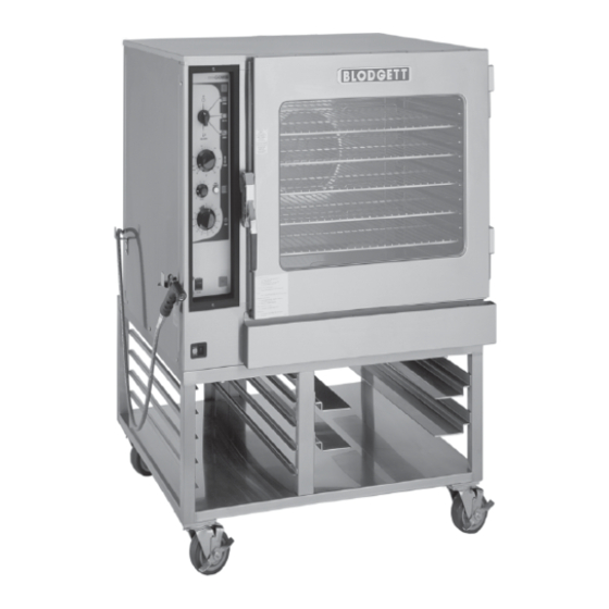
Introduction Oven Features BC14E shown Optional Semi-Automatic Deliming Figure 1 Control Panel Deliming Port (BC14E and BC14G only) Power Connection (BC14E and BC14EDS only) Fuses (BC14E only) Oven Door Gas Shutoff Drip Collector (BC14G only) Door Handle... -
Page 9: Installation
If you do not have a local distributor, please call Blodgett Combi at 0011-802-860-3700. -
Page 10: Owner's Responsibilities
Installation Owner’s Responsibilities Installation responsibilities prior to service 1. Oven(s) are uncrated, stacked (if applies) and put in place. startup inspection NOTE: Please refer to Leg Attachment and You are entitled to a free start-up inspection ser- Stacking. vice by our factory ASAP . Before a factory repre- sentative arrives to perform a startup procedure, Maximum shelf loading -- 60 lbs (27.3 Kg) the owner must already have satisfied the follow-... - Page 11 Installation Owner’s Responsibilities RATINGS -- GAS APPLIANCES -- BC14G/AA Gas Type Gas Input Voltage Phase Amps Motor U.S. and Canadian Installations 208-240 1/2HP 208-240VAC, 50/60 Hz Natural Steam --- 55,000 BTU/Hr Hot Air Hot Air --- 65,000 BTU/Hr 65 000 BTU/Hr 1/2HP 208-240VAC, 50/60 Hz Total --- 115,000 BTU/Hr 208-240...
- Page 12 Installation Owner’s Responsibilities RATINGS -- ELECTRIC APPLIANCES -- BC14E/AA and BC14EDS/AA Max Load (amps) Voltage Phase Motor 1/2HP 208-240VAC, 50/60 Hz 1/2HP 208-240VAC, 50/60 Hz 1/2HP 208-240VAC, 50/60 Hz 1/2HP 208-240VAC, 50/60 Hz 1/2HP 208-240VAC, 50/60 Hz 380/220 1/2HP 208-240VAC, 50/60 Hz 415/240 1/2HP 208-240VAC, 50/60 Hz 400/230...
-
Page 13: Oven Location And Ventilation
BC14G 1” 6” 6” distributor. If you do not have a local distributor, BC14GDS (25.4mm) (152.4mm) (152.4mm) please call Blodgett Combi at 0011-802-860-3700. B14G 0” 0” (0mm) 6” (0mm)* (152.4mm) * 0” (0mm) clearance from hose hooks... -
Page 14: Leg Attachment
Installation Leg Attachment LEG OPTIONS ATTACHMENT 1. Align the threaded stud on one of the front Legs are available in 4” (101mm), 6” (152mm) or legs to the bolt hole located in the bottom cor- 25” (635mm) lengths or low profile casters. ner of the appliance. -
Page 15: Caster Attachment
Installation Caster Attachment 1. Place a level on the floor where the casters are to rest. 2. Place shims under the low side until it is level. 3. Mount the shims between the casters and the oven as follows: a.) Align the shims and caster holes with the bolt holes. -
Page 16: Stacking
2. Attach the legs or casters to the bottom ap- NOTE: An optional gas manifold may be purchased pliance. See page 10. from Blodgett Combi. Order part number 3. Place the top appliance on the bottom ap- R9570. pliance. Be sure all four sides are flush. -
Page 17: Oven Leveling And Steam Connection
Installation Oven Leveling and Steam Connection OVEN LEVELING STEAM CONNECTION This oven should be set up in place. NOTE: BC14EDS and BC14GDS only. With any stand or oven, be certain that the surface Connect the appliance to a 40 to 50 psi maximum is level, even and solid. -
Page 18: Plumbing Connections
Installation Plumbing Connections WATER CONNECTION DRAIN CONNECTION NOTE: Hot water maximizes steam production but The steam vent assemblies are constructed of 2” DWV copper piping reduced to 1-1/2 DWV pipe. is not required. Cold water may be supplied to both inlets if hot water is not available. The steam vent should be run to an open floor drain avoiding flexible hose that could sag and al- Connect the appliance to quality water via a pres-... -
Page 19: Electrical Connections
Installation Electrical Connections ELECTRICAL CONNECTION Electric Models All Models A strain relief for the power supply cord is required. The installer must supply a cord bushing that meets NOTE: Electrical connections must be performed all Local and National installation standards. by a qualified installer only. -
Page 20: Gas Connections
Installation Gas Connections GAS PIPING Maximum Capacity of Iron Pipe in Cubic Feet of Natural Gas Per Hour A properly sized gas supply system is essential for (Pressure drop of 0.5 Inch W.C.) maximum oven performance. Piping should be sized to provide a supply of gas sufficient to meet Pipe Nominal Size, Inches the maximum demand of all appliances on the line... - Page 21 1/2 psig (3.45kPa). If you do not have a local distributor, please call Blodgett Combi at 0011-802-860-3700. The oven must be isolated from the gas supply piping system by closing its individual manual...
-
Page 22: Gas Hose Restraint
If the restraint is disconnected for any rea- If you do not have a local distributor, please call son it must be reconnected when the ap- Blodgett Combi at 0011-802-860-3700. pliance is returned to its original position. Quick Connect Attachment Plate... -
Page 23: Adjustments
Installation Adjustments Before applying power to the appliance for the first DOOR ADJUSTMENT time, check for the following conditions: The door catch may be adjusted in four directions, All electrical safety provisions have been ad- in and out, and up and down, using the following hered to and the electrical connections are procedure: correct. -
Page 24: Final Check Lists
Installation Final Check Lists WARNING!! Cold Water Supply Final check list must be performed by a qualified installer only. Hose and Spray Option ELECTRICAL CONTROL COMPARTMENT Voltage to appliance matches rating plate PLUMBING FINAL CHECK Incoming water pressure within appliance specification. - Page 25 Installation Final Check Lists OVEN OPERATIONAL TESTS Hot Air Mode Turn to HOT AIR mode and set thermostat to NOTE: Checks to be made by customer or autho- 400_F (204_C) and verify: rized service agent. Heat demand lamp is on. Cool Down Mode Oven is heating.
-
Page 26: Operation
They are the key to the from the appliance before removing the re- successful operation of your Blodgett Combi ap- straint cable. Reconnect the restraint after the pliance. oven has been returned to its original location. -
Page 27: Gas Controls
Operation Gas Controls CONTROLS IDENTIFICATION 1. GAS CONTROL SWITCH --- Used to turn gas 3. GAS OFF POSITION --- Press the switch into on or off. the O position. 2. GAS ON POSITION --- Press the switch into the I position. See View A BC14G Shown Figure 12... -
Page 28: Standard Controls
Operation Standard Controls CONTROLS IDENTIFICATION 1. POWER ON LAMP --- when lit indicates power to the unit is turned on. 2. MODE SELECTOR SWITCH --- turns power to the oven on or off. Allows selection of Steam, Hot Air, Combi or Cool Down Modes. 3. - Page 29 Operation Standard Controls OPERATION Steam on Demand 1. Turn the MODE SELECTOR Switch (2) to the How to set the Steam On Demand mode: desired function. While in the Hot Air or Combi mode, the unit can 2. Set the TIMER (8) to ON. be set to steam for a timed period.
-
Page 30: Optional Cook & Hold
Operation Optional Cook & Hold CONTROLS IDENTIFICATION 1. POWER ON LIGHT --- when lit indicates pow- er to the unit is turned on. 2. MODE SELECTOR SWITCH --- controls power to the oven and selection of steam, hot air and combi modes. - Page 31 Operation Optional Cook & Hold 20. DELIME LAMP --- Flashes when steam gener- 8. When all cook stages are complete the TIME ator deliming is needed. Remains steady DISPLAY (3) flashes 00:00, the TEMPERA- when deliming process is active. TURE DISPLAY (5) flashes 0 and an audible alarm sounds.
- Page 32 Operation Optional Cook & Hold STEAM ON DEMAND How to set the Steam On Demand mode: This feature is useful in many ways. A few are listed below. Most of the ideas came from our creative While in the Hot Air or Combi mode, the unit can customers.
- Page 33 Operation Optional Cook & Hold PROGRAMMING THE PRODUCT KEYS PROGRAMMING THE MANUAL KEY NOTE: Each product key can hold two programs: NOTE: The manual key may be used for manual one for steam and one for hot air/combi. Hot cooking and programmed for two prod- air programs can be used in combi.
-
Page 34: Optional Meat Probe
Operation Optional Meat Probe CONTROLS IDENTIFICATION 2. Turn the MEAT PROBE Switch (1) to ON. 3. To set the desired core temperature press the 1. MEAT PROBE SWITCH blue SET BUTTON (4) on the MEAT PROBE Controls power to the meat probe. CONTROL (2). -
Page 35: Maintenance
Maintenance Spray Bottle Operating Procedure NOTE: Only use a commercial oven cleaner/de- NOTE: Further information can be found in the in- greaser with the spray bottle. DO NOT use struction leaflet supplied with your spray chemicals that are not intended as oven bottle. -
Page 36: Cleaning And Preventive Maintenance
Maintenance Cleaning and Preventive Maintenance CLEANING THE INTERIOR Recommended cleaners: a.) ECOLAB Greasecutter Plus Daily Cleaning b.) CELLO EZ Clean Daily cleaning of the appliance is essential for sanita- c.) Diversey-Lever Advance Oven Cleaner tion, and to ensure against operational difficulties. The stainless steel cavity may corrode with improper cleaning of the oven. - Page 37 Insert the tact the factory, the factory representative or a lo- two screws to secure the fan guard. cal Blodgett Combi service company to perform maintenance and repairs should they be required. Remove and clean the blower wheel every 6 months.
-
Page 38: Deliming
Maintenance Deliming NOTE: The following procedures apply to models delimed. The Delime lamp will flash when the steam generator has been run for the preset inter- BC14E and BC14G only. val. The flashing Delime lamp does not impede the operation of the oven, as you can use the oven WARNING!! normally when the lap is flashing. - Page 39 Maintenance Deliming NOTE: The following procedures apply to models Model Ounces (pump) BC14E and BC14G only. BC14E 16 ounces (1 pump) DELIMING WITHOUT OPTIONAL ELECTRIC BC14G 16 ounces (1 pump) DELIMING PUMP NOTE: The Delime lamp must be flashing to start 4.
- Page 40 Maintenance Deliming 3. Place the deliming fluid reservoir in its location WARNING!! relative to the pump, as close as possible, and measure the length of tubing required to If the oven is hot, it must be placed in the reach from the pump inlet to the bottom of the cool down mode for 1 minute with the reservoir.
- Page 41 Maintenance Deliming 5. Attach one end of the tubing supplied to the pump outlet with a barbed fitting and hose clamps. Route the tubing to the oven inlet in such a way as to prevent contact with hot sur- faces, such as the oven flue. Cut the tubing to length and attach it to the inlet fitting with a hose clamp.
- Page 42 Maintenance Deliming 7. Fill the solution reservoir with a non-diluted de- DELIMING WITH OPTIONAL DELIMING PUMP liming agent such as Lime-Away by Eco-Labs NOTE: The following procedures apply to models or Lime-Out by US Chemical. BC14E and BC14G only. 8. Prime the delivery line by turning the oven into NOTE: The Delime lamp must be flashing to start COOL DOWN mode and depressing and holding the On Demand Steam button.
- Page 43 Maintenance Deliming DELIMING INTERVAL SETTING Refer to Figure 28 to determine the correct delim- NOTE: If you have the oven connected to a filter ing interval for your appliance. Find your location system, the water hardness may be re- and the corresponding potentiometer setting. duced.
- Page 44 Maintenance Deliming To set the deliming interval: 1. Remove power from the appliance. 2. Remove the two screws located on the side panel. Slide the control module forward. See Figure 29. 3. Turn the potentiometer to the required setting. See Figure 30. 4.
-
Page 45: Communication
A typical screen shot is A laptop computer can be used to view informa- shown below. Software (c) 2002 Blodgett Blodgett Combi BC --- 2 Control ROM Saved Data =========================== Version --- > 3 Model --- > 0 Startup Date--- >... - Page 46 Maintenance Communication To connect to the oven using a Laptop comput- er (Microsoft Windows OS) 1. Disconnect the appliance from the power source. 2. Remove (2) screws and slide the control panel forward. See Figure 33. 3. Boot up the computer. 4.
- Page 47 BC14E, BC14G et B14G Combi-Four/Étuve à Vapeur Manuel D’Installation --- Fonctionnement --- Entretien...
-
Page 48: Introduction
Introduction Le four-étuveur Combi de Blodgett Le four-étuveur Combi de Blodgett propose une De plus, vous pouvez utiliser deux ou trois fonc- toute nouvelle manière de cuire les aliments. Avec tions de manière séquentielle au cours d’une le four-étuveur Combi, vous pouvez choisir entre même cuisson. -
Page 49: Description Du Four-Étuveur Combi
Introduction Description du four-étuveur Combi À PROPOS DU FOUR-ÉTUVEUR FONCTIONNEMENT DU FOUR-ÉTUVEUR COMBI Les fours-étuveurs Combi de Blodgett sont des appareils haut de gamme fabriqués en acier La porte pratique du four est dotée d’un hublot et inoxydable de première qualité en faisant appel à possède un grand rayon d’ouverture. -
Page 50: Fonctionnalités Du Four
Introduction Fonctionnalités du four Modèle BC14E illustré Option de détartrage semi-automatique Figure 1 Panneau de commande Orifice de détartrage (BC14E et BC14G seulement) Prise d’alimentation (BC14E et BC14EDS seulement) Fusibles (BC14E seulement) Porte du four Fermeture du gaz Bac d’égouttage (BC14G seulement) Poignée... -
Page 51: Installation
S’il n’y a aucun détaillant dans votre région, veuil- lez communiquer avec Blodgett Combi au 0011-802-860-3700. -
Page 52: Responsabilités Du Propriétaire
Installation Responsabilités du propriétaire Responsabilités de l’installation avant l’inspec- 1. Le four est déballé, empilé (s’il y a lieu) et mis en place. tion de mise en service REMARQUE: Veuillez consulter la section Mon- Vous avez droit à une inspection de mise en servi- tage des pieds et Superposition. - Page 53 Installation Responsabilités du propriétaire CARACTÉRISTIQUES TECHNIQUES -- APPAREILS AU GAZ -- BC14G/AA Type de Entrée Tension Phase Intensité Moteur Installations canadiennes et américaines Naturel Vapeur --- 55 000 BTU/h 208-240 1/2 HP 208-240 V c.a., 50/60 Hz Air chaud Air chaud --- 65 000 BTU/h 65 000 BTU/h 1/2 HP 208-240 V c.a., 50/60 Hz Total --- 115 000 BTU/h...
- Page 54 Installation Responsabilités du propriétaire CARACTÉRISTIQUES TECHNIQUES -- APPAREILS ÉLECTRIQUES -- BC14E/AA et BC14EDS/AA Charge maximale Tension Fréquence Phase Moteur (ampères) 1/2 HP 208-240 V c.a., 50/60 Hz 1/2 HP 208-240 V c.a., 50/60 Hz 1/2 HP 208-240 V c.a., 50/60 Hz 1/2 HP 208-240 V c.a., 50/60 Hz 1/2 HP 208-240 V c.a., 50/60 Hz 380/220...
-
Page 55: Emplacement Du Four Et Mise De Niveau Et Ventilation
152,4 mm reil, veuillez communiquer avec votre détaillant. BC14GDS (1 po) (6 po) (6 po) S’il n’y a aucun détaillant dans votre région, veuil- lez communiquer avec Blodgett Combi au B14G 20 mm 0 mm 152,4 mm 0011-802-860-3700. (0 po)*... -
Page 56: Montage Des Pieds
Installation Montage des pieds OPTIONS MONTAGE 1. Alignez le goujon fileté situé sur l’un des pieds Les pieds sont offerts en différentes longueurs : avant avec le trou de boulon situé au coin infé- 101 mm (4 po), 152 mm (6 po) ou 635 mm (25 po) rieur de l’appareil. -
Page 57: Accessoire Des Roulettes
Installation Accessoire des roulettes 1. Placez un niveau sur le plancher où les roulet- tes seront installées. 2. Placez des cales sous le côté bas jusqu’à ce qu’il soit de niveau. 3. Montez les cales entre les roulettes et le four comme suit : a.) Alignez les cales et les trous des roulettes Ajoutez des cales selon les... -
Page 58: Superposition
Consultez la page 52. REMARQUE:Un collecteur de gaz optionnel est of- 3. Placez l’appareil du haut sur l’appareil du bas. fert par Blodgett Combi. Comman- Assurez-vous que les quatre côtés sont bien dez la pièce numéro R9570. alignés. -
Page 59: Mise De Niveau Du Four Et Branchement Del La Vapeur
Installation Mise de niveau du four et branchement del la vapeur MISE DE NIVEAU DU FOUR BRANCHEMENT DE LA VAPEUR La préparation du four doit se faire à l’emplace- REMARQUE:BC14EDS et BC14GDS seulement ment choisi. Brancher l’appareil sur une source extérieure de Assurez-vous que la surface de l’emplacement vapeur de 276---345 kPa (40---50 PSI) maximum, en accord avec les codes locaux ou de province. -
Page 60: Raccordement De La Plomberie
Installation Raccordement de la plomberie RACCORDEMENT À L’EAU RACCORDEMENT DU DRAIN REMARQUE:L’utilisation d’eau chaude maximise Les évents à vapeur se composent de tuyaux de cui- vre de 2 popour système d’égout se rétrécissant à la production de vapeur, mais elle 1-1/2 po. -
Page 61: Raccordement À L'électricité
Installation Raccordement à l’électricité Tous les modèles Modèles électriques REMARQUE:Seul un technicien qualifié peut effec- Le cordon d’alimentation nécessite un protecteur de cordon. Le responsable de l’installation doit fournir tuer le raccordement à l’électricité. un manchon pour le cordon qui respecte les normes Avant de procéder au raccordement à... -
Page 62: Raccordement Au Gaz
Installation Raccordement au gaz CONDUITE DE GAZ seur en gaz local si vous avez des questions à ce sujet. Il est essentiel d’avoir un circuit d’alimentation en gaz approprié afin que le four puisse donner un Capacité maximale en gaz naturel d’une rendement maximal. - Page 63 S’il n’y a aucun détaillant local dans votre ré- périeure à 1/2 lb/po (3,45 kPa). gion, veuillez communiquer avec Blodgett Combi au 0011-802-860-3700. Isolez le four de la tuyauterie d’alimentation en gaz en fermant son robinet d’arrêt pendant les essais de PRESSION DE GAZ Dimensions de l’orifice au...
-
Page 64: Câble D'immobilisation Du Tuyau À Gaz
S’il n’y a aucun détaillant dans votre région, veuil- fois l’appareil remis en place. lez communiquer avec Blodgett Combi au 0011-802-860-3700. Raccord rapide Plaque de fixation (fixez au Conduite d’alimentation... -
Page 65: Ajustements
Installation Ajustements Avant de mettre l’appareil sous tension pour la AJUSTEMENT DE LA PORTE première fois, effectuez les vérifications suivantes: Le loquet de la porte s’ajuste dans directions, soit Toutes les normes de sécurité ont été respec- vers l’avant et l’arrière et aussi vers le haut et vers tées et les connexions électriques sont appro- le bas. -
Page 66: Liste De Vérification Finale
Installation Liste de vérification finale ATTENTION !! Alimentation en eau froide Seul un installateur qualifié peut effectuer les étapes suivantes de la liste de vérifica- Boyau et pulvérisateur tion. (optionnels) COMPARTIMENT DES COMMANDES ÉLECTRIQUES La tension de l’alimentation électrique de l’ap- pareil est conforme aux spécifications énon- cées sur la plaque. - Page 67 Installation Liste de vérification finale ESSAIS DE FONCTIONNEMENT DU FOUR Mode Hot Air (air chaud) Réglez l’appareil sur le mode Hot Air (air chaud) et REMARQUE: Le client ou le réparateur agréé doivent réglez le thermostat sur 204_C (400_F), et vérifiez effectuer les vérifications suivantes.
-
Page 68: Fonctionnement
Fonctionnement Renseignements sur la sécurité des appareils au gaz Les renseignements contenus dans la présente Que faire en cas de panne de courant : section sont destinés au personnel d’exploitation Placez tous les commutateurs à la position OFF. qualifié, c.-à-d. les personnes qui ont soigneuse- NE TENTEZ PAS de faire fonctionner votre ap- ment lu ce manuel et qui se sont familiarisées avec pareil avant le rétablissement du courant. -
Page 69: Commandes Du Gaz
Fonctionnement Commandes du gaz IDENTIFICATION DES COMMANDES 1. INTERRUPTEUR DE COMMANDE DE GAZ 3. POSITION DE GAZ ARRÊTÉ --- Appuyez sur --- Utilisé pour mettre en marche et arrêter le l’interrupteur pour l’amener sur la position O. gaz. 2. POSITION DE GAZ EN MARCHE --- Appuyez sur l’interrupteur pour l’amener sur la position Voir la vue A Modèle BC14G illustré... -
Page 70: Commandes Standard
Fonctionnement Commandes standard IDENTIFICATION DES COMMANDES 1. VOYANT DE MISE SOUS TENSION --- Il s’al- lume quand l’unité est sous tension. 2. SÉLECTEUR DE MODE --- Établit et coupe l’alimentation du four. Permet la sélection des modes Steam (vapeur), Hot Air (air chaud), Combi (combinaison) ou Cool Down (refroi- dissement). - Page 71 Fonctionnement Commandes standard FONCTIONNEMENT 9. Le sélecteur de mode constitue aussi l’inter- rupteur principal d’alimentation. À la position 1. Placez le SÉLECTEUR DE MODE (2) à la fonc- OFF (arrêt), l’appareil n’est pas fonctionnel. tion désirée. Vapeur sur demande 2. Réglez la MINUTERIE (8) à la position ON (marche).
-
Page 72: Cuisson Et Pause En Option
Fonctionnement Cuisson et Pause en Option IDENTIFICATION DES CONTRÔLES 1. VOYANT DE MISE SOUS TENSION --- Il s’al- lume quand l’unité est sous tension. 2. SÉLECTEUR DE MODE --- Il permet de mettre en marche ou d’arrêter le four, ainsi que de sélectionner les modes Vapeur [Steam], Air chaud [Hot Air], Combi ou Refroidissement [Cool down]. - Page 73 Fonctionnement Cuisson et Pause en Option 14. TOUCHE ARRET --- Appuyer sur cette touche température pour une rétention pour stopper les alarmes, arrêter momentané- maximale de l’humidité, puis rég- ment le four ou annuler les cycles de cuisson. ler sur la seconde étape pour le brunissement.
- Page 74 Fonctionnement Cuisson et Pause en Option FONCTIONNEMENT PROGRAMMÉ VAPEUR SUR DEMANDE REMARQUE:Référez-vous à la page 29 pour les in- Dans le mode Air chaud ou Combi, l’appareil peut être réglé pour chauffer à la vapeur pour une pé- structions de programmation. riode temporisée.
- Page 75 Fonctionnement Cuisson et Pause en Option PROGRAMMATION DES TOUCHES DE 7. Appuyer sur les TOUCHES FLÉCHÉES DE TEMPÉRATURE (7) pour régler la tempéra- PRODUITS ture de cuisson de la deuxième étape. REMARQUE:Chaque touche de produit peut être 8. Appuyer sur les TOUCHES FLÉCHÉES DE LA programmée pour deux programmes: MINUTERIE (4) pour régler le temps de cuis- Vapeur et Air chaud/Combi.
- Page 76 Fonctionnement Cuisson et Pause en Option PROGRAMMATION DE LA TOUCHE CUISSON MANUELLE REMARQUE:La touche Cuisson manuelle peut 6. Appuyer sur les TOUCHES FLÉCHÉES DE TEMPÉRATURE (7) pour régler la tempéra- être utilisée pour la cuisson en mode ture de cuisson de la deuxième étape. manuel et programmée pour deux produits, Vapeur et Air chaud/Combi.
-
Page 77: Sonde Thermique Optionnelle
Fonctionnement Sonde thermique optionnelle IDENTIFICATION DES CONTRÔLES 4. Régler MINUTERIE RESTE MARCHE. Le processus de cuisson marche 1. INTERRUPTEUR DE LA SONDE À VIANDE automatiquement. Contrôle la marche ou l’arrêt de la sonde à Quand la température à coeur choisie est at- viande. -
Page 78: Entretien
Entretien Procédure de fonctionnement du pulvérisateur REMARQUE:Utilisez seulement un produit net- REMARQUE:Pour obtenir de plus amples rensei- toyant/dégraissant de four commer- gnements, consultez le livret d’ins- cial avec le pulvérisateur. IL NE FAUT tructions fourni avec le pulvérisateur. PAS utiliser de produit chimique qui n’est pas conçu pour nettoyer les ATTENTION !! fours. -
Page 79: Nettoyage Et Entretien Préventif
Entretien Nettoyage et entretien préventif NETTOYAGE DE L’INTÉRIEUR se et la décoloration légère avec un bon nettoyeur industriel non toxique adapté à l’acier inoxydable. Nettoyage quotidien Appliquez le produit lorsque le four est froid et frot- tez toujours dans le sens du grain du métal. Vous Le nettoyage quotidien du four est essentiel pour pouvez nettoyer les grilles, les supports et la roue respecter les conditions sanitaires minimales et... - Page 80 Entretien Nettoyage et entretien préventif 3. Tournez la garde de ventilateur dehors Indicateur “CLEAN OVEN” du B14 Boilerless L’indicateur ”CLEAN OVEN” informe l’utilisateur que le four a été en service pendant une période préprogrammée et il est temps de le nettoyer. Il est nécessaire de complètement nettoyer l’intérieur en raison des minerais de l’eau qui s’accumuler- ont.
-
Page 81: Détartrage
Entretien Détartrage REMARQUE:Les procédures ci-dessous s’appli- Ce four est fourni avec un voyant de détartrage pour indiquer le moment où le générateur de va- quent uniquement aux modèles peur doit être détartré. Le voyant de détartrage cli- BC14E et BC14G. gnote lorsque le générateur de vapeur a été... - Page 82 Entretien Détartrage DÉTARTRAGE SANS L’OPTION DE POMPE DE respond à un (1) pompage. Utilisez le tableau ci-dessous. DÉTARTRAGE ÉLECTRIQUE REMARQUE:Les procédures ci-dessous s’appli- Modèles Onces (pompage) quent uniquement aux modèles BC14E et BC14G. BC14E 16 onces (1 pompage) REMARQUE:Le voyant de détartrage doit clignoter BC14G 16 onces (1 pompage) pour commencer ce processus.
- Page 83 Entretien Détartrage 3. Mettez le réservoir du fluide de carbonatation AVERTISSEMENT !! à sa place relativement à la pompe, aussi près que possible, et mesurez la longueur de tuyau Si la cavité du four est chaude, il faut mettre nécessaire pour aller depuis l’entrée de la le four dans le mode de refroidissement pompe jusqu’au fond du réservoir.
- Page 84 Entretien Détartrage 5. Attachez un bout du tuyau fourni à la sortie de la pompe à l’aide d’un raccord à pointes et un collier de serrage. Posez le tuyau jusqu’à l’en- trée du four de façon à éviter tout contact avec les surfaces chaudes, telles que le tuyau d’évacuation des fumées.
- Page 85 Entretien Détartrage 7. Remplissez le réservoir à solution avec l’agent DÉTARTRAGE AVEC L’OPTION DE POMPE DE de carbonatation non-dilué, tel que Lime- DÉTARTRAGE Away produit par Eco-Labs ou Lime-Out de REMARQUE:Les procédures ci-dessous s’appli- US Chemical. quent uniquement aux modèles 8.
- Page 86 Entretien Détartrage RÉGLAGE DE L’INTERVALLE DE DÉTARTRAGE Reportez-vous à la Figure 27 pour déterminer l’in- ou moins calcaire. Ajustez l’intervalle de détartra- tervalle de détartrage approprié à votre appareil. ge en fonction de la qualité de l’eau utilisée. Cherchez votre lieu et le réglage correspondant REMARQUE:Si le four est connecté...
- Page 87 Entretien Détartrage Pour régler l’intervalle de détartrage : 1. Mettez l’appareil hors tension. 2. Retirez les deux vis situées sur le panneau la- téral. Glissez le module de commande vers l’avant. Voir la Figure 28. 3. Amenez le potentiomètre sur le réglage né- cessaire.
- Page 88 Une vue d’écran typique est mande. Un ordinateur portable peut être utilisé montrée ci-dessous. pour visualiser des informations concernant cer- Software (c) 2002 Blodgett Blodgett Combi BC --- 2 Control ROM Saved Data =========================== Version --- > 3 Model --- > 0 Startup Date--- >...
- Page 89 Entretien Communications Pour connecter un ordinateur portable au four (système d’exploitation Windows de Microsoft) 1. Débranchez l’appareil de la source d’alimen- tation électrique. 2. Retirez (2) vis et glissez le panneau de com- mande vers l’avant. Voir la Figure 32. 3.
- Page 90 INSERT WIRING DIAGRAM HERE PLACER SCHÉMA DE CÂBLAGE...
Need help?
Do you have a question about the Synergy BC14E and is the answer not in the manual?
Questions and answers