Table of Contents
Advertisement
Quick Links
Advertisement
Table of Contents

Related Manuals for AmpliVox Otowave 302+


Summary of Contents for AmpliVox Otowave 302+
- Page 1 INSTRUCTION FOR USE D-0126546-C...
-
Page 2: About This Manual
READ THIS OPERATING MANUAL BEFORE ATTEMPTING TO USE THE INSTRUMENT. This manual is valid for the Otowave 302+ (applies from firmware version 1.0.0.085410 onwards – see System Information screen). This product is manufactured by: Amplivox Ltd 3800 Parkside, Solihull Parkway, Birmingham Business Park, Birmingham, West Midlands, B37 7YG www.amplivox.com... -
Page 3: Table Of Contents
TABLE OF CONTENTS TABLE OF CONTENTS ABOUT THIS MANUAL TABLE OF CONTENTS INTRODUCTION 1.1. HANK YOU 1.2. NTENDED APPLICATIONS 1.3. ONTRAINDICATIONS 1.4. ACCESSORIES TANDARD AND OPTIONAL 1.5. UARANTEE 1.6. ARNINGS UNPACKING AND INSTALLATION 2.1. ENERAL 2.2. ARKINGS 2.3. AFETY INSTRUCTIONS 2.3.1. - Page 4 TABLE OF CONTENTS 4.1. ENERAL PRECAUTIONS 4.2. WITCHING THE INSTRUMENT ON AND OFF 4.3. ISPLAYS 4.4. ROFILE STRUCTURE 4.4.1. General 4.4.2. Changing Profiles 4.4.3. Copy Profile Settings from one to another 4.4.4. REset Profile Settings to Factory Default 4.4.5. Display Mode 4.5.
- Page 5 7.4. COUSTIC REFLEX TESTING EMC GUIDANCE & MANUFACTURER’S DECLARATION SAFETY PRECAUTIONS TO TAKE WHEN CONNECTING OTOWAVE 302+ 10. APPENDIX A – 1000 HZ TYPANOMETRY & MEATUS COMPENSATION 10.1. YMPANOMETRIC PROPERTIES 10.2. YMPANOMETRIC EASUREMENTS 10.3. CALAR VS VECTOR BASELINE 10.4. REFERENCE POINT FOR BASELINE VALUE 11.
-
Page 6: Introduction
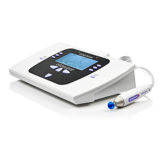
INTRODUCTION 1. INTRODUCTION 1.1. THANK YOU Thank you for purchasing an Amplivox Otowave 302+, a desktop-controlled impedance meter that will give many years of reliable service if treated with care. 1.2. INTENDED APPLICATIONS This instrument is designed for use by trained personnel only, such as audiologists, ENT surgeons, doctors, general practitioners, hearing aid dispensers, child health professionals and hearing healthcare professionals with a similar level education. -
Page 7: Standard And Optional Accessories
1.4. STANDARD AND OPTIONAL ACCESSORIES Shipping documentation will reference the stock number quoted above, and images of the parts alongside the relevant stock number are available on the Amplivox website (www.amplivox.com). The required fitting instructions are supplied with each part. -
Page 8: Guarantee
All Amplivox instruments are guaranteed against faulty materials and manufacture. The instrument will be repaired free of charge for a period of three years from the date of dispatch if returned, carriage paid, to the Amplivox service department. Return carriage is free of charge for customers in the UK and chargeable for overseas customers. -
Page 9: Unpacking And Installation
2.1. GENERAL Please check the contents of the shipping carton against the delivery note to make sure that all items ordered have been included. If anything is missing, please contact the distributor who supplied the tympanometer or Amplivox if purchased directly. -
Page 10: Safety Instructions
Amplivox Ltd. is aware that safety rules within individual organisations vary. If a conflict exists between the instructions in this manual and the rules of the organisation using this instrument, the more stringent rules should take precedence. -
Page 11: Environmental Factors
No parts of the equipment can be serviced or maintained while in use with the patient. Connect only accessories purchased from Amplivox Ltd. to the Otowave 302+. Only accessories which have been stated by Amplivox Ltd. to be compatible are allowed to be connected to the device. -
Page 12: Electrical And Electrostatic Safety
In particular a Separation Device is required when a network connection is made. The requirement for the Separation Device is defined in IEC 60601-1 clause 16. Do not use any additional multiple socket-outlet or extension cord. Use only the Amplivox Mains Power Adaptor. 2.3.5. ELECTROMAGNETIC COMPATIBILITY (EMC) -
Page 13: Miscellaneous
UNPACKING AND INSTALLATION To guarantee that the Otowave 302+ works properly, the instrument should be checked and calibrated at least once a year. The transducers supplied with the tympanometer are specifically calibrated with it; if these transducers are changed recalibration will be required. The service and calibration must be performed by an authorised service technician. -
Page 14: Connections
Mains AC/DC Adapter 2.5mm power jack Please note: Only connect the accessories supplied with the instrument or supplied by Amplivox or an Amplivox distributor. These parts have been tested for use with the Amplivox Otowave 302+ tympanometer for compliance with the standards IEC 60601-1 and IEC 60601-1-2. -
Page 15: Controls And Indicators (Base Unit)
UNPACKING AND INSTALLATION 2.5. CONTROLS AND INDICATORS (BASE UNIT) The Otowave 302+ consists of an LCD screen, buttons in groups to operate the instrument and three status LEDs. Power indicator LED Lights up as soon as the instrument is powered through the mains adapters (also when the instrument is switched off). -
Page 16: The Probe
UNPACKING AND INSTALLATION 2.6. THE PROBE 2.6.1. CONTROLS AND INDICATORS (PROBE) Indicator light Illuminates depending on functionality of the instrument Function button Quick view of the test settings currently used or change of baseline mode. Probe tip with ear tip 2.6.2. -
Page 17: Light Indicators
2.9. CHOOSING THE CORRECT EAR TIP SIZE Amplivox YouTube video is available for assistance on how to choose the right ear tip. The probe tip must be fitted with a new ear tip before it is presented to a patient’s ear canal. If a contralateral reflex stimulus is to be applied, fit a new ear tip to the contralateral transducer before presenting it to the patient’s opposite... -
Page 18: Hardware Installation
UNPACKING AND INSTALLATION Please note: The probe tip must be fitted with a new ear tip before it is presented to a patient’s ear canal. If a contralateral reflex is to be applied, fit a new ear tip to the contralateral transducer before presenting it to the patient’s opposite ear canal. -
Page 19: Date And Time
UNPACKING AND INSTALLATION 2.11.2. DATE AND TIME The Otowave 302+ is equipped with a real-time clock. Before use, please set the date & time to local values in order to ensure that test data and calibration status are correctly identified. 2.12. -
Page 20: Principles Of Operation
PRINCIPLES OF OPERATION 3. PRINCIPLES OF OPERATION 3.1. OTOSCOPIC EXAMINATION A suitably-qualified health care professional should perform a thorough otoscopic examination to establish that the condition of the ear is suitable for the test options selected and that no contraindications are present. The latter would include obstruction of the external ear canal due to excessive wax and/or hairs, both of which would need to be removed. -
Page 21: Acoustic Reflex Measurement
PRINCIPLES OF OPERATION 3.4. ACOUSTIC REFLEX MEASUREMENT Using the same principle as in tympanometry measures, it is also possible to establish whether an acoustical reflex is present. The acoustic reflex is caused by the contraction of the stapedial muscle as a response to high-intensity stimulation of the ear. -
Page 22: Using The Otowave 302
USING THE OTOWAVE 302+ USING THE OTOWAVE 302+ 4.1. GENERAL PRECAUTIONS When operating the instrument, please observe the following general precautions: CAUTION 1. Use this device only as described in this manual. 2. Use only the disposable ear tips designed for use with this instrument. Always use a new ear tip for each patient to avoid cross-contamination. -
Page 23: Switching The Instrument On And Off
USING THE OTOWAVE 302+ 4.2. SWITCHING THE INSTRUMENT ON AND OFF Select the on/off button for 1 second to switch the instrument on. You will see a small hourglass in the middle of the display indicating that the instrument is powering on. No warm-up time is required, although a short diagnostic routine will run for a few seconds. -
Page 24: Changing Profiles
USING THE OTOWAVE 302+ When marked with a *, the profil has been modified. PROFILE TEST SETTINGS Adult: Tympanometry: 226 Hz, 200 daPa/s speed Ipsilateral Reflexes: always measure, 0.5, 1, 2 kHz (Multilevel, 100 dB in 5 dB steps, autostop enabled, 0.03 ml threshold) Contralateral Reflexes: Disabled Child:... -
Page 25: Reset Profile Settings To Factory Default
USING THE OTOWAVE 302+ COPY ALL SETTINGS (SWEEP + REFLEX) 1.) To overwrite all settings, access 2.) Choose the profile you want to 3.) Select the profile you want to the COPY function from the MAIN overwrite: the current selected one copy the settings from. -
Page 26: Display Mode
USING THE OTOWAVE 302+ RESET ONLY 1 SETTING (SWEEP OR REFLEX) 1.) To reset just one setting, access the sweep or reflex settings. In there you will find a DEFAULT function. 2.) Choose the profile you want to reset: the current selected one or all available profiles. After selection, confirm the overwrite. -
Page 27: Test Settings
USING THE OTOWAVE 302+ 4.5. TEST SETTINGS 4.5.1. GENERAL The SETTINGS SUBMENU contains the following settings: • Sweep Settings (Tympanometry only) • Reflex Settings (Acoustic reflex only) • Default Sweep + Reflex • Copy Sweep + Reflex Function (Profiles) • Rename Profile When selecting one of the sub settings, the target profile is required to be selected first in order to define if the CURRENT profile shall be... -
Page 28: Sweep Settings
USING THE OTOWAVE 302+ 4.5.2. SWEEP SETTINGS Amplivox YouTube video is available for assistance on how to use different test settings in tympanometry. ITEM DESCRIPTION DEFAULT(ADULT) Speed: The rate of change of air pressure may be selected to be 100daPa/s 200 daPa/s 200daPa/s or 300daPa/s. -
Page 29: Reflex Settings
USING THE OTOWAVE 302+ 4.5.3. REFLEX SETTINGS Amplivox YouTube video is available for assistance on how to add ipsilateral reflexes to test protocol. ITEM DESCRIPTION DEFAULT(ADULT) Level Mode: ONE LEVEL will only test one single level at the selected frequencies. -
Page 30: System Settings
USING THE OTOWAVE 302+ Copy: Overwrite the sweep settings of your current profile from one of the other 5 profiles. Refer to section 4.4.3 for further information about the Copy function. 4.6. SYSTEM SETTINGS Access the system settings from the HOME screen. ITEM DESCRIPTION DEFAULT... -
Page 31: Daily) Check
USING THE OTOWAVE 302+ 4.7. (DAILY) CHECK The operation of the Otowave 302+ should be checked daily using the 4-in-1-test cavity assembly supplied with the instrument. Select the DAILY CHECK option in the main menu and wait until INSERT PROBE is displayed. Insert the probe, without an ear tip, into any of the holes of the test cavity. -
Page 32: Performing A Test
USING THE OTOWAVE 302+ 4.9. PERFORMING A TEST 4.9.1. SELECTING THE EAR SIDE Having selected the required test settings a typical tympanogram measurement and reflex tests are carried out as follows. Select NEW TEST by pushing S1. Select the ear(s) required for test (BOTH signifies LEFT followed by RIGHT), using S1, or S3. - Page 33 USING THE OTOWAVE 302+ STANDARD EAR SEAL CHECK EXTENDED EAR SEAL CHECK The default STANDARD option only shows if a seal could The EXTENDED EAR SEAL CHECK shows a number of bars be obtained. indicating the level of the seal. The probe should be adjusted in the ear until two or more bars are shown for LOW and HIGH.
-
Page 34: Understanding The Tympanometry Test Result
USING THE OTOWAVE 302+ As soon as the probe is removed from the ear, the test result for the ear measured will be displayed on the screen. Please note: If BOTH EARS had been selected to be tested, the test on the other ear will be performed after the test review ►... -
Page 35: Performing Tympanometry And Acoustic Reflex Testing
4.9.4. PERFORMING TYMPANOMETRY AND ACOUSTIC REFLEX TESTING Amplivox YouTube video is available for assistance on how to run a test. Before starting an acoustic reflex test, a tympanogram is performed so that the ear canal pressure will be set to the value that gave the peak admittance. -
Page 36: Understanding The Acoustic Reflex Test Result
USING THE OTOWAVE 302+ 4.9.5. UNDERSTANDING THE ACOUSTIC REFLEX TEST RESULT ► ◄ The navigation key are required to navigate in the reflex result screens. The acoustic reflex result screens will always start to The combined view shows a smaller tympanogram and show the tympanogram first. - Page 37 USING THE OTOWAVE 302+ Tympanogram on the left-hand side and the four reflex traces shown on the right. Ear side, L for left and R for right. Values defining compliance curve based on cursor position and the Baseline Mode • Pk (Peak): Volume in ml or mmho, pressure in daPa •...
-
Page 38: Process Results
4.10.1. GENERAL Amplivox YouTube video is available for assistance on how to process test data. After a test has been finished, the data can be printed and/or stored to the internal database of the instrument or transferred to NOAH or Amplivox ampliSuite. - Page 39 USING THE OTOWAVE 302+ A three-character identifier is used for the record. This is also used as the reference for the patient’s name on the printed record and for data transferred to a computer. The identifier would typically be the patient’s initials, and as the tympanometer uses a combination of this identifier and the date/time of a test to refer to stored records this same identifier may be used for different tests for the same patient.
-
Page 40: Re)View The Last Test(S)
USING THE OTOWAVE 302+ 4.11. (RE)VIEW THE LAST TEST(S) The Otowave 302+ offers a short-term memory that allows you to store the last test that has been conducted and is automatically overwritten by the next new test. The symbols ✓ or X are used to signify whether results are available for each ear. -
Page 41: Database
4.12.1. GENERAL Amplivox YouTube video is available for assistance on how to process test data. Up to 36 tests can be stored in the Otowave 302+ internal database. Records stored in the database of the Otowave 302+ can be listed, viewed, printed or deleted using the DATABASE. -
Page 42: Delete Records
USING THE OTOWAVE 302+ VIEW RECORD SEND TO PRINTER DELETE RECORD The symbols ✓ or X are used to Confirm the SENT TO PRINTER When DELETE RECORD is selected a signify whether results are available selection as soon as the printer is confirmation deletion for each ear. -
Page 43: Print Records
To transfer test results stored within the Otowave 302+ to a NOAH database, the Amplivox NOAH Impedance module must be installed on to a computer. Alternatively, Amplivox ampliSuite allows data to be transferred to a computer and subsequently viewed, annotated & printed. This software is supplied on a USB stick which also includes this operating manual. -
Page 44: Troubleshooting
TROUBLESHOOTING 5. TROUBLESHOOTING If a fault condition cannot be cleared, the operator is cautioned against repeatedly starting the instrument. Please note: Refer to the installation & operating instructions provided with ampliSuite, NOAH Impedance Module software for details of the data transfer operation and errors that may occur. PROBLEM CAUSE SOLUTION(S) - Page 45 • and base unit cannot be Ensure connection established. between printer and base unit is established. If you experience difficulty in resolving faults the equipment distributor (or Amplivox if purchased directly) should be consulted. 44 OTOWAVE 302+ INSTRUCTION FOR USE...
-
Page 46: Routine Maintenance
ROUTINE MAINTENANCE 6. ROUTINE MAINTENANCE 6.1. GENERAL MAINTENANCE PROCEDURES The performance and safety of the instrument will be maintained if the following recommendations for care and maintenance are observed: 1. It is recommended that the instrument go through at least one annual service, to ensure that the acoustical, electrical and mechanical properties are correct. -
Page 47: Cleaning The Otowave 302
ROUTINE MAINTENANCE 6.2. CLEANING THE OTOWAVE 302+ CAUTION • Use caution while cleaning. • Before cleaning, remove the Otowave 302+ from mains power. • Single use components such as ear-tips do not require cleaning. • Do not allow any liquid to enter any part of the instrument or accessories. •... -
Page 48: Accessories/Replacement Parts
Loss or damage in return shipment to Amplivox Ltd. shall be at purchaser's risk. In no event shall Amplivox Ltd. be liable for any incidental, indirect or consequential damages in connection with the purchase or use of any Amplivox Ltd. product. -
Page 49: Calibration And Return Of The Instrument
Amplivox Ltd. . This warranty is in lieu of all other warranties, express or implied, and of all other obligations or liabilities of Amplivox Ltd. Amplivox Ltd. does not give or grant, directly or indirectly, the authority to any representative or other person to assume on behalf of Amplivox Ltd. -
Page 50: Technical Specifications
7. TECHNICAL SPECIFICATIONS 7.1. STANDARD AND REGULATORY Medical CE mark The CE mark indicates that Amplivox Ltd. Meets the requirements of Annex II of the Medical Device Regulation 2017/745. TÜV Product Service, Identification No. 123, has approved the quality system. -
Page 51: Tympanometry
TECHNICAL SPECIFICATIONS printed and/or sent to a computer, parameters used for analysis, 128 bit Globally Unique Identifier (GUID) Data presentation: Records listed in reverse chronological order (latest first), with indication of data stored as described above Printing Supported printer: Sanibel MPT-II Interface: Cable supplied Information printed:... - Page 52 TECHNICAL SPECIFICATIONS Number reflex levels 110/105/100dBHL max, with 5dB or 10dB steps presented below the selected 95/90/85dBHL max, with 5dB steps maximum and step size(s) available: General THD: < 5 % Reflex analysis Reflex pass/fail at each level tested; maximum amplitude of each reflex;...
-
Page 53: Emc Guidance & Manufacturer's Declaration
EMC GUIDANCE & MANUFACTURER’S DECLARATION 8. EMC GUIDANCE & MANUFACTURER’S DECLARATION CAUTION • This instrument is suitable in hospital environments except for near active HF surgical equipment and RF shielded rooms of systems for magnetic resonance imaging, where the intensity of electromagnetic disturbance is high •... - Page 54 EMC GUIDANCE & MANUFACTURER’S DECLARATION Guidance and manufacturer’s declaration – electromagnetic emissions The Otowave 302+ Tympanometer is intended for use in the electromagnetic environment specified below. The customer or user of the Otowave 302+ Tympanometer should assure that it is used in such an environment. Emissions test Compliance Electromagnetic environment –...
- Page 55 EMC GUIDANCE & MANUFACTURER’S DECLARATION Immunity test IEC 60601 test Compliance Electromagnetic environment – guidance level level <5% U <5% U Voltage dips, short Mains power quality should be that of a typical interruptions and commercial or hospital environment. If the user of the (>95% dip in (>95% dip in voltage variations...
- Page 56 EMC GUIDANCE & MANUFACTURER’S DECLARATION Guidance and manufacturer’s declaration – electromagnetic immunity (2) The Otowave 302+ Tympanometer is intended for use in the electromagnetic environment specified below. The customer or user of the Otowave 302+ Tympanometer should assure that it is used in such an environment. Immunity test IEC 60601 Compliance...
- Page 57 EMC GUIDANCE & MANUFACTURER’S DECLARATION Guidance and manufacturer’s declaration – electromagnetic immunity (2) Field strengths from fixed transmitters, such as base stations for radio (cellular/cordless) telephones and land mobile radios, amateur radio, AM and FM radio broadcast and TV broadcast cannot be predicted theoretically with accuracy.
-
Page 58: Safety Precautions To Take When Connecting Otowave 302
SAFETY PRECAUTIONS TO TAKE WHEN CONNECTING OTOWAVE 302+ 9. SAFETY PRECAUTIONS TO TAKE WHEN CONNECTING OTOWAVE 302+ Please note that if connections are made to standard equipment like printers and networks, special precautions must be taken in order to maintain medical safety. Please follow instructions given in this section. Diagram 1: Otowave 302+ used with the medically-approved mains adapter Medical Mains Adapter Otowave 302+... -
Page 59: Appendix A - 1000 Hz Typanometry & Meatus Compensation
APPENDIX A – 1000 HZ TYPANOMETRY & MEATUS COMPENSATION 10. APPENDIX A – 1000 HZ TYPANOMETRY & MEATUS COMPENSATION 10.1. TYMPANOMETRIC PROPERTIES Tympanometric measurements of the ear are affected by a large number of physiological characteristics, but from a clinical perspective the three most important, physical properties impacting the outcome of a tympanometrical measurement are: 1. - Page 60 APPENDIX A – 1000 HZ TYPANOMETRY & MEATUS COMPENSATION ��_���� = ��_�������� − ��_���� When considering the general case, including probe tone frequencies at higher frequencies than 226Hz, the above subtraction of the effect of the ear canal air volume is more complicated. In mathematical terms, a complex subtraction is required, which involves taking into account the G and B components separately.
-
Page 61: Scalar Vs Vector Baseline
APPENDIX A – 1000 HZ TYPANOMETRY & MEATUS COMPENSATION Contrast this with Figure 2 where the phase angles are very different and a scalar subtraction would erroneously give a value close to zero, instead of the length of the vector in orange Figure 2: 1 kHz probe tone: Although the susceptance values B and B are the same as in the 226 Hz diagram, the distance... -
Page 62: Reference Point For Baseline Value
APPENDIX A – 1000 HZ TYPANOMETRY & MEATUS COMPENSATION 10.4. REFERENCE POINT FOR BASELINE VALUE An additional feature of the Otowave 302+ not found on other screening tympanometers is that the user can decide whether to use −400 or + 200 daPa as the reference point for the baseline value. 61 OTOWAVE 302+ INSTRUCTION FOR USE... -
Page 63: Appendix B -Baseline Mode
APPENDIX B –BASELINE MODE 11. APPENDIX B –BASELINE MODE 11.1. GENERAL The Otowave 302+ can display tympanograms in a variety of graphical formats allowing the operator to choose the most appropriate for the patient under examination. This is achieved by altering the DISPLAY MODE and the meatus compensation (or BASELINE OFFSET). The DISPLAY MODE determines how the tympanogram trace is derived from the raw data, and the baseline offset selects the pressure to which the meatus compensation is referenced (either -400daPa or +200daPa). -
Page 64: 1000 Hz Tympanometry
APPENDIX B –BASELINE MODE 11.3. 1000 HZ TYMPANOMETRY 11.3.1. SCALAR MODE – Y-COMPENSATION For 1 kHz operation a similar scalar display mode is available as used for 226Hz (Y-only compensation). This mode is generally preferred when testing very young children. 2S MODE 4S MODE 11.3.2. - Page 65 Copyright © 2021 Amplivox Ltd All rights reserved. No part of this publication may be reproduced or transmitted in any form or by any means without the prior written permission of Amplivox Ltd. D-0126546-C...
Need help?
Do you have a question about the Otowave 302+ and is the answer not in the manual?
Questions and answers