Hitachi PC-LH3A Operation & Installation Manual
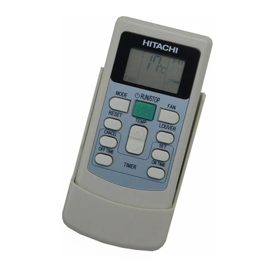
Wireless remote control switch (unidirectional type)
Hide thumbs
Also See for PC-LH3A:
- Installation and operation manual (12 pages) ,
- Installation and operation manual (85 pages)
Table of Contents
Advertisement
Quick Links
Operation & Installation Manual for
Wireless Remote Control Switch (Unidirectional Type)
Model: PC-LH3A, PC-LH3B
IMPORTANT NOTICE:
l HITACHI pursues a policy of continuing improvement in design and performance of products.
The right is therefore reserved to vary specifications without notice.
l HITACHI cannot anticipate every possible circumstance that might involve a potential hazard.
l This kit is designed for combination of HITACHI Air Conditioners.
Do not use this kit itself or combination of other companies Air Conditioners.
l This product is designed for standard air conditioning only.
DO NOT use this product for specific purposes, such as restoring foods, animals & plants, precision
devices, art objects, etc.
l No part of this manual may be reproduced without written permission.
l Signal words are used to identify levels of hazard seriousness.
Definitions for identifying hazard levels are provided below with their respective signal words.
NOTE
l Perform the test run whether there is abnormality or not after the installation work is completed.
The usage and the maintenance should be explained to a user according to "Installation & Maintenance
Manual" of the indoor unit. Describe to keep this installation manual also.
l It is assumed that this kit will be installed and serviced by English speaking people. If this is not the case,
the customer should add safety, caution and operating signs in the native language.
l If you have any questions, contact your distributor or dealer of HITACHI.
l This manual gives a common description and information for this wireless remote control switch which you
operate as well as for other models.
l DO NOT install the unit in the following places. It causes failure to the unit in many cases.
* Places where oil (including machinery oil) mist and steam drifts.
* Places where a lots of sulfide gas drifts such as in hot spring.
* Places where inflammable gas may generate or flow.
* Places where air contains high salt contents as coast regions.
* Places where with atmosphere of acidity or alkalinity.
l Pay attention to the following points when the unit is installed in a hospital or other facilities where
electromagnetic wave generates from medical equipment.
* Do not install the unit in the place where the electromagnetic wave is directly radiated to the electrical
box, remote control switch cable or remote control switch.
* Install the unit at least 3 meters away from electromagnetic wave such as a radio.
l DO NOT install the unit in the place where the air flow directly catches to animals or plants.
It could be the cause of adverse affect to animals or plants.
: DANGER indicates a hazardous situation which, if not avoided,
will result in death or serious injury.
: WARNING indicates a hazardous situation which, if not avoided,
could result in death or serious injury.
: CAUTION, used with the safety alert symbol, indicates a hazardous
situation which, if not avoided, could result in minor or moderate injury.
: NOTICE is used to address practices not related to personal injury.
: NOTE is useful information for operation and/or maintenance.
1
P5416537
Advertisement
Table of Contents

Related Manuals for Hitachi PC-LH3A


Summary of Contents for Hitachi PC-LH3A
- Page 1 Model: PC-LH3A, PC-LH3B IMPORTANT NOTICE: l HITACHI pursues a policy of continuing improvement in design and performance of products. The right is therefore reserved to vary specifications without notice. l HITACHI cannot anticipate every possible circumstance that might involve a potential hazard.
- Page 2 ● Do not turn ON the power source, unless the preparation for test running is completed. ● Read this manual carefully before installation work for correct performance. ● Read this manual together with the “Installation & Maintenance Manual” of the indoor unit. 1.
- Page 3 The set temperature, timer operation, position of air louver, operation mode, air flow mode, etc., are indicated. The fan speed setting “HIGH2” will not be shown on PC-LH3A. The diagram of the display shown on the left is for explanation purposes only. The display will differ during actual operation.
- Page 4 Within approx. 50 (Directivity) (2) The indication lamp (yellow) on the TIMER FILTER DEF receiver part of the indoor unit turns Transmitting EMERGENCY PC-LH3A ON for an instant when the indoor unit indication " " PC-LH3B flashes once. receives the commands. HEAT...
- Page 5 5. Identifying Indoor Units Installed Side by Side Operation Turn OFF the power source completely before performing the dip switch setting for receiver kit. If not, it may cause an electric shock. "Identified" In the case that two indoor units are installed side by Indoor Unit side, the commands from the wireless remote control Indoor...
- Page 6 7. Installing onto the Wall or Pillar ATTENTION: When the commands are sent by the controller hooked onto the wall, the receiver of the indoor unit may not receive the commands depending on the installation place. 1) Select the suitable place for handling and install the controller with the customer’s acceptance. Do not install the controller at the places as follows.
- Page 7 It may happen that some indoor Control Example of Simultaneous Operation of Multiple Units units remain unchanged. © 2015 Johnson Controls-Hitachi Air Conditioning Technology (Hong Kong) Ltd. P5416537, 2015 Printed in Japan...
Need help?
Do you have a question about the PC-LH3A and is the answer not in the manual?
Questions and answers