Table of Contents
Advertisement
Advertisement
Table of Contents

Related Manuals for Plymovent OS-3


Summary of Contents for Plymovent OS-3
- Page 1 Control Box OS-3 AUTOMATIC SYSTEM CONTROL User manual www.plymovent.com...
-
Page 2: Table Of Contents
4.4 Primary Wiring Procedures (Control Wiring) ............... 7 4.5 Transformer Wiring Procedure ..................7 4.6 Pressure Switch Procedure ....................8 4.7 Temperature Switch Procedure ..................8 Wireless Control System Procedure ................... 8 Maintenance ........................9 Troubleshooting ......................9 Spare Parts ........................9 Electrical diagram ......................9 Disposal ........................9 00000116183/300421/D OS-3... -
Page 3: General Precautions
If this equipment is used in a manner not specified by the manufacturer, the protection provided by the equipment may be impaired. In no event will Plymovent be responsible or liable for indirect or consequential damages resulting from the use or application of this equipment. The examples and diagrams in this manual are included solely for illustrative purposes. Because of the many variables and requirements associated with any particulate installation, Plymovent cannot assume responsibility or liability for actual use based on the examples and diagrams. - Page 4 EN - ORIGINAL INSTRUCTION All rights reserved. The information given in this document has been collected for the general convenience of our clients. It has been based on general data pertaining to construction material properties and working methods known to us at the time of issue of the document and is therefore subject at anytime to change or amendment, and the right to change or amend is hereby expressly reserved. Changes may be made with or without notification, it is the users responsibility to ensure they have attained the most recent copy of this document for their files. The instructions in this publication only serve as a guideline for installation, use, maintenance and repair of the product mentioned on the cover page of this document. This publication is to be used for the standard model of the product of the type given on the cover page. Thus the manufacturer cannot be held responsible for any damage resulting from the application of this publication to the version actually delivered to you. This publication has been written with great care. However, the manufacturer cannot be held responsible, either for any errors occurring in this publication or for their consequences. 00000116183/300421/D OS-3...
-
Page 5: Preface
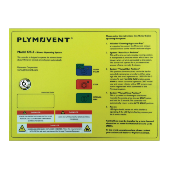
Identification of The Product Suitable for outdoor use The identification plate contains, among other things, the following data: Transport of The Unit - product name - serial number The OS-3 control box is delivered as self-contained exhaust - supply voltage and frequency system controller complete with functions for manual run, and - power consumption automatic start with delay off and stop. General Description The manufacturer cannot be held liable for any damage to the unit due to shipping or mishandling. Always handle the unit and The OS-3 control box is an energy saving control unit designed the accompanying options and/or accessories, if any, with care. to be used for controlling exhaust fans in vehicle exhaust systems, with or without a particle filtration system. Together with a pressure switch and optional temperature switch, this energy saving controller makes a fully automatic system for the 00000116183/300421/D OS-3... -
Page 6: Product Description
This temperature rise occurs when a running vehicle is attached - This user manual should always be kept with the product, as to the system, and will ensure the system stays running while well as a duplicate copy be kept by the fire department or city the vehicle is in operation. service department after installation. - The examples and diagrams in this manual are included solely 2.1.3 Automatic Mode for illustrative purposes. Because of the many variables and requirements associated with any particular installation, This mode of operation allows for everyday use when exiting the Plymovent cannot assume responsibility or liability for actual fire station for emergency calls. When the engine is started, the use based on the examples and diagrams. pressure switch closes, this completes the circuit to the control - No patent liability is assumed by Plymovent with respect to use box causing the fan to turn on. When the engine turns off or the of information, circuits, or equipment described in this manual. apparatus leaves the fire station, the pressure and/or - Reproduction of the contents of this manual, in whole or in temperature in the system decreases and the control box part, without prior written permission of Plymovent is enteres into a delay off mode. Once the timer has completed its prohibited. -
Page 7: Installation
- All installations must meet any and all applicable local laws, regulations, standards and requirements. Unpacking - It is the responsibility of the installing party to ensure that all codes are met during the installation of this control system. Check that the product is complete. The package should contain: Any inspections required are the sole responsibility of the - OS-3 control box installing party. - door key - Inspect the product and check it for damage. - Verify the functioning of the safety features. Electric connection - Never install the product in front of entrances and exits which Connect the OS-3 in accordance with the separately supplied must be used for emergency services. electrical diagram. -
Page 8: Primary Wiring Procedures (Control Wiring)
Automation Systems (BAS). Always ensure power is off and all required procedures for 4.4.2 Pressure Switch / Temperature Switch (engine facility (such as lock out tag out) are properly followed before start/stop) making any adjustments to the control system. The pressure switch and optional temperature switch, which is sold separately, will be wired to terminal block 1 and 2. If more WARNING! than one pressure/temperature switch is utilized in a system Procedures which, if not carried out with the they must be wired in parallel to achieve proper operation. necessary caution, may damage the product and/or cause serious personal injury. NOTE: Control wires supplying terminal block 1 and 2 must be a minimum of 16 AWG/1.29 mm², smaller wire sizing will result in improper system operation. 00000116183/300421/D OS-3... -
Page 9: Pressure Switch Procedure
Wi-Fi systems. The learning receiver can learn up to 24 different accurately adjust the pressure switch start the vehicle and check transmitters. The receiver shall operate on 24 VAC and be that the fan starts immediately, turn off vehicle and the exhaust mounted in a non-metallic enclosure with a clear see through lid fan should run for maximum 5 minutes. approximately 8’ to 10’ (2.4m to 3m) above the finished floor level, directly above the OS-3 Automatic Controller. NOTE: If exhaust fan does not start, adjust the pressure switch by turning adjusting screw clockwise (in) 1/8 of a turn and 4.8.2 Electrical Wiring Connections restart the vehicle. If the fan still does not start repeat procedure. If fan starts when the vehicle is not running decrease Connect the red wire labeled 12-24V to terminal 24V on terminal pressure setting on pressure switch by turning adjustment screw strip TB1, connect the black wire labeled GRND to terminal 0 on counter clockwise (out) 1/4 turn. terminal strip TB1, connect the blue wire labeled C to terminal 1 on terminal strip TB1, connect the orange wire labeled NO to Temperature Switch Procedure terminal 2 on terminal strip TB1 inside OS-3 control box. 4.7.1 Optional Temperature Switch For Wireless System programming refer to the Wireless Control System Product Manual. Plymovent has incorporated an optional temperature switch, which senses the exhaust gas temperature generated by the 00000116183/300421/D OS-3... -
Page 10: Maintenance
MAINTENANCE The OS-3 requires no specific maintenance. TROUBLESHOOTING If the OS-3 does not function correctly, please contact your local authorized dealer/technician. SPARE PARTS Please refer to Table 1 on page 10 to view the spare parts available for the OS-3. Fig. 8.2 Terminal Detail Fig. 7.1 Exploded view • A - F3 • B - Transformer • C - F1/F2 • D - Contactor • E - Overload Relay • F - Adjusting Hole for Timer • G - Circuit Board • H - Membrane ELECTRICAL DIAGRAM Please refer to Figures 8.1-8.4 (below) and Figure 1 on page... - Page 11 Table 1 Spare Parts Rated Amp Plymovent Voltage/ Overload load for ctrl Contactor F1 & F2*** F3*** Number Phase* Relay box** OS-3 for 1/2 HP fan 115V/1ph 00000100389 00000100390 00000116071 00000101409 230V/1ph 00000100389 00000101443 00000116054 00000101409 230V/3ph 1.78 00000100389 00000101443...
- Page 12 Overload load for ctrl Contactor F1 & F2*** F3*** Number Phase* Relay box** 00000116138 575V/3ph 6.93 00000100389 00000100390 00000116067 00000101409 OS-3 for 10 HP fan 00000116131 230V/1ph 38.8 00000102474 00000116837 00000116054 00000101409 00000116132 230V/3ph 25.8 00000102474 00000102477 00000116054 00000101409 00000116133 460V/3ph 11.7...
- Page 13 Figure 1 Wiring Chart 00000116183/300421/D OS-3...
- Page 14 1,174 (357.8) TEV-3110-60 10.6 108 (32.9) FUA-4700-1-AM 132 (40.2) FUA-4700-2-AM 528 (160.9) 813 (247.8) 16.7 173 (52.7) 15.2 132 (40.2) TEV-559-60 333 (101.4) 519 (158.1) 24.2 191 (58.2) 146 (44.5) TEV-585-60 230 (70.1) 352 (107.2) 30.8 150 (45.7) 182 (55.4) TEV-745-60 287 (87.4) 288 (87.7) 46.2 158 (48.1) 193 (58.8) TEV-768-60 305 (92.9) 472 (143.8) *If wire length is longer than distance listed, upsize to next larger AWG Note: Guidelines are subject to change without notice. Data supplied from our primary motor supplier. Please confirm at time of order. Plymovent assumes no liability for any electrical installation, all local, city, and the 2014 National Electric Code must be followed. This chart is a minimum standard and to be used as a guideline only. Based on a 3% voltage drop for branch circuits. 00000116183/300421/D OS-3...
- Page 15 86 (26.2) FUA-2101-AM 179 (54.5) 217 (66.1) FUA-2701-AM 70 (21.3) FUA-3001-AM 143 (43.5) 174 (53) 92 (28) TEV-359-60 13.2 119 (36.2) 145 (44.1) FUA-4701-AM 18.7 134 (40.8) TEV-3110-60 163 (49.6) 325 (99) 30.8 130 (39.6) TEV-559-60 158 (48.1) 209 (63.7) 144 (43.8) TEV-585-60 175 (53.3) 347 (105.7) 184 (56) TEV-745-60 140 (42.6) 286 (87.1) *If wire length is longer than distance listed, upsize to next larger AWG **2014 NEC Table 430.248 does not list 460 volt single phase motors Note: Guidelines are subject to change without notice. Data supplied from our primary motor supplier. Please confirm at time of order. Plymovent assumes no liability for any electrical installation, all local, city, and the 2014 National Electric Code must be followed. This chart is a minimum standard and to be used as a guideline only. Based on a 3% voltage drop for branch circuits. 00000116183/300421/D OS-3...
- Page 16 00000116183/300421/D OS-3 www.plymovent.com...
Need help?
Do you have a question about the OS-3 and is the answer not in the manual?
Questions and answers